With the growth in the Internet of Things (IoT) products, the number of applications requiring an estimate of range between two wireless nodes in indoor channels is growing very quickly as well. Therefore, localization is becoming a red hot market today and will remain so in the coming years. See the big picture of localization for general solutions to this problem.
One question that is perplexing is that many companies now a days are offering cm level accurate solutions using RF signals. The conventional wireless nodes usually implement synchronization techniques which can provide around $\mu s$ level accuracy and if they try to find the range through timestamps, the estimate would be off by
$$1 \mu s \times 3 \times 10^8 m/s = 300 m$$
where $3\times 10^8 m/s$ is the approximate speed of an electromagnetic wave. So how are cm level accurate solutions being claimed and actually delivered?
This is a classic example of the simplest of signals solving the most complex of problems.
In this article, my target is to explain the fundamentals behind this high resolution ranging in the easiest of manners possible. Needless to say, while each product would have its own unique signal processing algorithms, the fundamentals still remain the same.
The Big Picture
For the sake of providing the big picture, remember that there are other methods available, the best of which are based on optical interferometry. Then, there are ultrasound, optical and hybrid options available as well. RF is the cheapest solution though and there is nothing better than getting accurate measurements using the RF waves.
The following techniques are most widely used in RF domain.
- Rx Signal Strength Indicator (RSS)
- Time of arrival (ToA)
- Phase of arrival (PoA) – a special case of ToA
- Time Difference of Arrival (TDoA)
- Angle of Arrival (AoA)
While I do not explain each of the above in detail (Google is your friend), I summarize their pros and cons below (anchors are wireless nodes with known positions).
| Technique | Pros | Cons |
| RSSI | Simple hardware, no synchronization required, info provided by most PHY chips | Highly inaccurate and environment specific |
| ToA | Highly accurate | Time synchronization required among anchors and target node |
| PoA | Extremely accurate, low cost | Sensitive to phase noise and impairments |
| TDoA | Great accuracy, no target node synchronization | Tight synchronization among all anchors |
| AoA | Extra dimension relaxes timing and phase constraints | Expensive hardware and less accurate |
As a final comment, all range estimation methods need a reference point. Anchors provide this reference when an accurate measurement of position is needed. If it is just the range from another node that is of interest, any node can use its own reference. This is the situation we assume in this article.
What is a Timestamp?
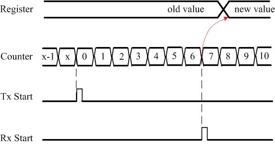
A typical embedded device comes with a counter and a register. The value of the counter increments/decrements as driven by an oscillator. When an increment counter reaches the maximum value (0xF…FF), or a decrement counter reaches the minimum value (0x0…00), it overflows and starts counting again. If a desirable event occurs, say a message arrival event driven by a Rx start interrupt, the value of the counter can be captured and stored in a register that can be later accessed to find the time of that event – according to the node’s own reference clock.
As an example, consider the following Figure where
- the timestamp value is captured in Register
- the Counter is an incremental counter
- Tx Start is an event that resets the counter, and
- Rx Start is an event that captures the Counter value to Register.

Figure 1: The counter, register and Tx and Rx start events
If you don’t know much about electronics, it is enough to know that event times can be recorded at a node and accessed for processing later.
Setup
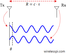
The ranging setup in this discussion consists of two nodes that can exchange timestamps with each other through the wireless medium as shown in Figure below.
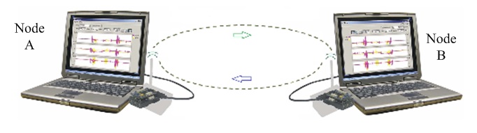
Figure 2: Two nodes exchanging timestamps with each other
The distance between the two nodes is $R$ while the time of flight from one node to another is $\tau$. Consequently,
$$R = \tau \cdot c$$
We denote the real time by $t$, Node A’s time by $T_A$ and Node B’s time by $T_B$. Since each node starts at a random time, there is a clock offset between its time as compared to the real time.
$$T_A = t + \phi_A$$
$$T_B = t + \phi_B$$
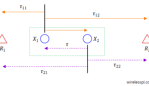
Refer to the next Figure to observe how the chain of events unfolds.
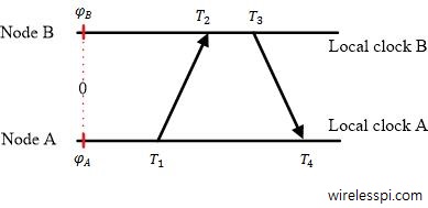
Figure 3: The chain of events with their corresponding timestamps exchanged between Node A and Node B
Any node can start its counter at any given time. So to set a reference point at an arbitrary real time 0, the time offset of Node A is $\phi_A$ while that of of Node B is $\phi_B$.
1. Node A sends its local timestamp $T_1$ to Node B at real time $t_1$, where
$$T_1 = t_1 + \phi_A$$
2. Node B receives this packet at real time $t_2$ and records its local time $T_2$, where
$$T_2 =t_2 + \phi_B$$
Clearly,
$$t_2 = t_1 + \tau,\qquad or \qquad \tau = t_2-t_1$$
Therefore, we can write
$$T_2-T_1 = t_2 +\phi_B- t_1-\phi_A $$
Defining $T_2-T_1$ as $\Delta T_{A->B}$ and $\Delta \phi$ as $\phi_B – \phi_A$ (the clock offset between two nodes),
$$\Delta T_{A->B} = \tau + \Delta \phi \quad —— \quad \text{Eq (1)}$$
It is important to write the equation in the above form because all we know is the observation $\Delta T_{A->B}$. We do not know $t_1$, $t_2$, $\tau$, $\phi_A$ and $\phi_B$.
3. After a processing delay, Node B sends its local timestamp $T_3$ at real time $t_3$ to Node A.
4. Node A records it at $T_4$ at actual time $t_4$. Since $t_4 = t_3+\tau$,
$$T_4 -T_3 = t_4+\phi_A – t_3 – \phi_B$$
which can be written in terms of $\Delta T_{B->A}=T_4-T_3$ as
$$\Delta T_{B->A} = \tau – \Delta \phi \quad —— \quad \text{Eq (2)}$$
Adding Eq (1) and Eq (2) yields the estimate of delay.
$$\hat \tau = \frac{1}{2}\Big(\Delta T_{A->B} + \Delta T_{B->A}\Big)$$
Now it is clear that the time base of Node A serves as the reference for estimating this delay. Research literature refers to this approach as a ‘two-way message exchange‘. To pay tribute to Tolkien, I call it ‘There and Back Again‘.
Performance
I performed some ranging experiments with Atmel AT86RF215 radios with a clock rate of 8 MHz. That implies that one such tick takes $1/(8 \times 10^6)$ $=$ $125 ns$. In terms of distance, this is $125 ns \times 3\times 10^8$ $=$ $37.5$ m. Gradually increasing the distance, a divide by two operation and rounding off the results generated the following results.
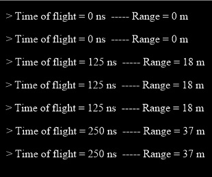
Figure 4: Results for a ranging experiment with an 8 MHz clock
Assume that a 100x accuracy, say $37.5$ cm, is needed. Then, we need a clock generating timestamps at a rate of 800 MHz. That kind of expense and power, however, is more suited to computing applications and not to an embedded device.
In conclusion, we cannot afford a high rate clock but still desire a high resolution.
The Arrival of the Phase of Arrival
In the spirit of time of arrival, this method is known as the phase of arrival. First, observe that we already have access to something similar to a high resolution clock – a continuous wave (CW). Consider a simple sinusoid at GHz frequency and just plot its sign. It looks very much like a very high rate clock.

Figure 5: Sign of a simple continuous wave is similar to a high rate clock
Now again consider two wireless nodes that are exchanging continuous waves instead of timestamps in the following manner.
1. Node A sends a continuous wave $\cos (2\pi F_1 t)$ of frequency $F_1$ at its time $T_1$ (real time $t_1$) to Node B. Using $T_1 = t_1 + \phi_A$, its phase is given by
$$2\pi F_1 T_1 = 2\pi F_1 t_1 + 2\pi F_1 \phi_A$$
where $2\pi F_1 \phi_A$ is just a constant and could easily be expressed as a single term $\phi’_A$. As opposed to timestamps case, it is not required, neither it is easy, to measure the phase $2\pi F_1 T_1$ explicitly.
2. Node B receives this continuous wave at real time $t_2$ when the phase of its own local reference at frequency $F_1$ at its local time $T_2$, where $T_2 =t_2 + \phi_B$, is
$$2\pi F_1 T_2 = 2\pi F_1 t_2 + 2\pi F_1 \phi_B$$
Using $t_2 = t_1 + \tau$, Node B employs some signal processing algorithm to measure the phase difference between the two continuous waves as
$$\Delta \theta_{A->B} = 2\pi F_1(T_2-T_1) = 2\pi F_1 \tau + 2\pi F_1\Delta \phi\quad —— \quad \text{Eq (3)}$$
It is important to write the equation in the above form because all
we know is the phase difference $\Delta \theta _{A->B}$. We do not know anything else.
3. After a processing delay, Node B sends a continuous wave in the reverse direction.
4. Node A measures the phase difference
$$\Delta \theta_{B->A} = 2\pi F_1 \tau – 2\pi F_1 \Delta \phi \quad —— \quad \text{Eq (4)}$$
Adding Eq (3) and Eq (4) yields the estimate of delay.
$$\hat \tau = \frac{1}{2\cdot 2\pi F_1}\Big(\Delta \theta_{A->B} + \Delta \theta_{B->A}\Big)\quad —— \quad \text{Eq (5)}$$
That was so easy, so fast and so accurate. But the world is not that simple.
The Rollover Problem
The solution to the accuracy problem creates a problem of its own. Remember we said that when an increment counter reaches the maximum value (0xF…FF), or a decrement counter reaches the minimum value (0x0…00), it overflows and starts counting again. So if a clock is very fast, it overflows more quickly and resets again. It might even do so when the signal on the reverse path might not have returned! The same is the case with the sinusoids.
For example, a continuous wave at 2.4 GHz would roll over every $1/(2.4 \times 10^9) \times 3 \times 10^8$ $=$ $12.5$ cm. Any distance greater than 12.5 cm would be impossible to measure.
Introducing More Carriers
To solve this rollover problem, assume $\Delta \theta = \Delta \theta_{A->B} + \Delta \theta_{B->A}$ and start with plugging Eq (5) in the range expression.
$$ R = c\cdot \hat \tau = c \cdot \frac{1}{2\cdot 2\pi F_1} \Delta \theta$$
This can be simplified using $c=F_1 \lambda_1$ as
$$R = \frac{\lambda_1}{2} \frac{\Delta \theta}{2\pi} $$
Now we can break the phase $\Delta \theta$ into an integer part and a fractional part because $\Delta \theta = 2\pi n + (\Delta \theta)_{\text{frac},F_1}$, where $n$ is the number of integer wavelengths spanning the distance $R$ while $(\Delta \theta)_{\text{frac},F_1}$ is the phase corresponding to the remaining fractional distance. Thus, the above equation can be written as
$$R = \frac{\lambda_1}{2}\left(n + \frac{(\Delta \theta)_{\text{frac},F_1}}{2\pi}\right)$$
Writing the fractional phase as a function of range
$$\Delta \theta_{\text{frac},F_1} = 2\pi\left(2R\frac{F_1}{c} – n\right)\quad —— \quad \text{Eq (6)}$$
The rollover unwrapping problem is now reduced to cancelling $n$ from the above equation. This can be easily accomplished by sending another tone at frequency $F_2$ that would generate the result
$$\Delta \theta_{\text{frac},F_2} = 2\pi\left(2R\frac{F_2}{c} – n\right)$$
The above two equations can now be solved to cancel $n$ and create an effect equivalent to sending a single tone with a very large wavelength or very low frequency $F_2-F_1$.
$$\Delta \theta_{\text{frac},F_2} – \Delta \theta_{\text{frac},F_1} = 2\pi\left(2R\frac{F_2-F_1}{c} \right)$$
The range is now found to be
$$R = \frac{c}{4\pi}\cdot \frac{\Delta \theta_{\text{frac},F_2} – \Delta \theta_{\text{frac},F_1}}{F_2-F_1}$$
Having eliminated the phase rollover, we are interested in maximum range that can be unambiguously estimated through the above equation. Clearly, this depends on the frequency difference between the two continuous waves. Also, remember that $\Delta \theta_{\text{frac},F_2} – \Delta \theta_{\text{frac},F_1}$ can attain a maximum value of $2\pi$. Then, for example, for a 2 MHz difference, i.e., $F_2-F_1=2\times 10^6$, the unambiguous range is
$$R = \frac{3\times 10^8}{4\pi}\cdot \frac{2\pi}{2\times 10^6}=75 m$$
The Phase Slope Method
To combat interference and multipath in indoor channels, a number of different continuous waves can be used and their results can be stitched together to form a precise range estimate. This is plotted in Figure below.
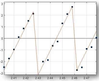
Figure 6: Phase vs frequency plot
After taking a number of measurements, a plot of phases versus frequencies is drawn. Similar to Eq (6), we can write
$$\Delta \theta_{\text{frac},F_k} = 2\pi\left(2R\frac{F_k}{c} + \text{constant}\right)$$
where the constant term arises instead of $n$ as it might not be the same for all frequencies. However, the slope of the curve is still given by
$$\text{slope} = \frac{4\pi}{c}\cdot R$$
from which the range can be found as
$$R = \frac{c}{4\pi} \cdot \text{slope}$$
This is why it is known as the Phase Slope method.
- It is relatively costly to implement due to a number of back and forth transmissions (equal to the number of CWs employed) but it is very accurate because indoor channels are frequently susceptible to interference. A wider range of frequencies ensures resilience against interference through the added redundancy, as explained in detail here.
- More importantly, a wider bandwidth combats the multipath problem through higher resolution of arriving echoes in time domain after taking the transform of this phase data.
- Finally, this method works even in the absence of synchronization among nodes as detailed here.
On this topic, you might also enjoy the article on Frequency Modulated Continuous-Wave (FMCW) radar.
When we say that for a clock rate of 8MHz, one tick corresponds to 37.5m distance. Isn’t this the minimum range that can be resolved/measured?
However, incase of using sinusoidal signal, you refer this distance as maximum/unambiguous range that can be measured owing to the counter reset issue as you described (which makes sense).
However, I’m confused whether the distance corresponding to one tick or one time period of clock rate or sinusoidal signal, respectively, maps to the minimum distance that can be measured or to the maximum/unambiguous range that can be measured?
Since, minimum and unambiguous range are two different things. Kindly shed some light on it. Thanks.
It is the unambiguous range. I don’t see any limits on the minimum distance that can be measured. Do you have any reason due to which there must be a limit on the measurable minimum distance?
Let’s say the sampling rate is same as the clock rate i.e. 8MHz. Which implies that one tick or one sample corresponds to 125ns and 18m in distance (considering two-way travel).
Let’s say that nodeB is located 10m away from nodeA. 10m of range translates to around 66ns of two-way time between nodeA and nodeB. For the ideal case, considering no processing delay at nodeB, it will take around 66ns to receive the reply signal at nodeA from nodeB. However, nodeA couldn’t sample that signal since it’s clock rate is going to wait until 125ns to pick the next sample, thereby missing any signal that arrives before its sample period time. Which, according to my understanding, gives rise to the limit on the measurable minimum distance.
Please correct me if I’m wrong. Thanks
So what you are referring to is known as range binning, something similar to quantization in ADCs. It can be reduced by averaging and interpolation. You can read the details on the effect of sampling in the report “RF Ranging for Location Awareness” Technical Report No. UCB/EECS-2009-69.
Thanks for sharing.
Hi, nice Article!
I am a little confused about Phase of Arrival method. Do we actually measure the timestamps T1, T2, T3, and T4 with uC and calculate the phase difference from these timestamps using equations 3 and 4? Or do we actually measure the phase difference directly with uC?
No, we don’t measure the timestamps in phase based approach. Instead, we measure the phase of the carrier wave that is unaffected after downconversion to baseband. It’s only the way we apply the phase difference equations that is quite similar to timestamp difference equations.