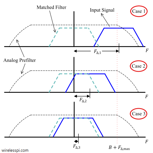
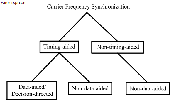
We have discussed before that carrier phase synchronization is done at the end of the Rx signal processing chain due to the very nature of the DSP implementation. And that almost all DSP based phase synchronization algorithms are timing-aided. Timing acquisition implies knowing the symbol boundaries in the Rx sampled waveform which is equivalent to identifying the optimal sampling instants where the eye opening is maximum and Inter-Symbol Interference (ISI) from the neighbouring symbols is zero. In the case of Carrier Frequency Synchronization (CFO), this is not true. From a previous post on the effect of CFO, we know that
Continue readingTag: Frequency Recovery
What is Carrier Frequency Offset (CFO) and How It Distorts the Rx Symbols
In Physics, frequency in units of Hz is defined as the number of cycles per unit time. Angular frequency is the rate of change of phase of a sinusoidal waveform with units of radians/second. \begin{equation*} 2\pi f = \frac{\Delta \theta}{\Delta t} \end{equation*} where $\Delta\theta$ and $\Delta t$ are the changes in phase and time, respectively. A Carrier Frequency Offset (CFO) usually arises due to two reasons. The video below also explains this concept. [Frequency mismatch between the Tx and Rx oscillators] No two devices are the same and there is always some difference between the manufacturer’s nominal specification and the
Continue readingPhase Locked Loop (PLL) in a Software Defined Radio (SDR)
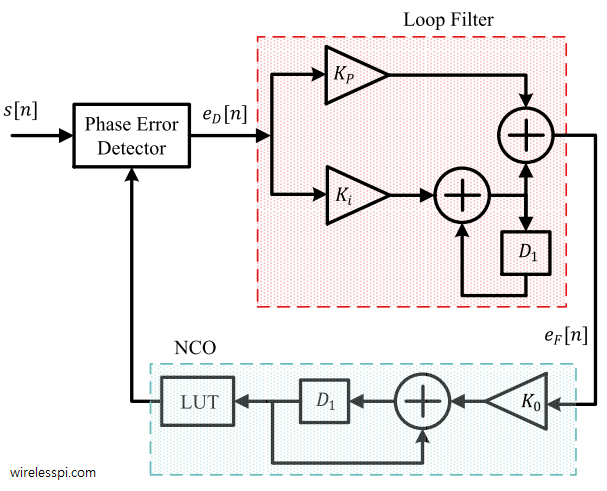
IBM Watson and Google DeepMind are the most complex computers that, some believe, will try to run the world in a distant future. A PLL on the other hand is the simplest computer that actually runs so much of the world as a fundamental component of intelligent electronic circuits. The PLL was invented by the French engineer Henri de Bellescize in 1932 when he published his first implementation in the French journal L’Onde Electrique. A Phase Locked Loop (PLL) is a device used to synchronize a periodic waveform with a reference periodic waveform. In essence, it is an automatic control
Continue readingBasics of Synchronization
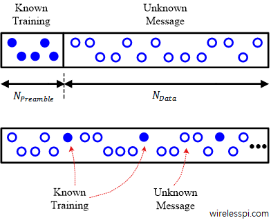
In every digital communication system, the Tx has the easier role of signal generation while the Rx has the tougher job of figuring out the intended message. Just like solving a puzzle told by someone. Estimating and compensating for the frequency, phase and timing offsets between Tx and Rx oscillators is one such challenge. The solution can be designed depending on many factors such as some part of data is known (called a ‘training sequence’) or not, the synchronizer needs to be one-shot or continuously updating, and so on. Known Data Availability Depending on the availability of known data, synchronization
Continue readingQuadrature Amplitude Modulation (QAM)
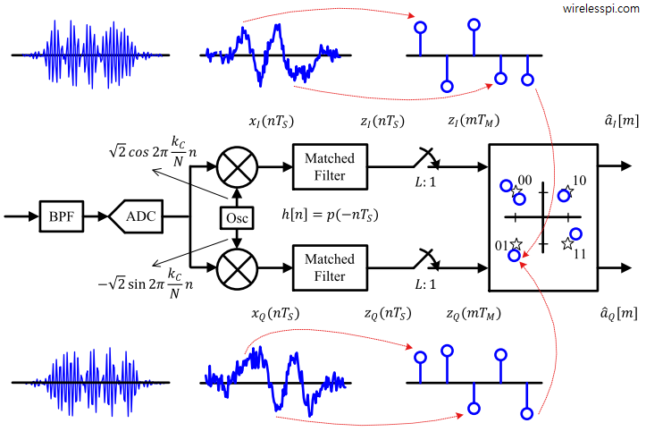
Quadrature Amplitude Modulation (QAM) is a spectrally efficient modulation scheme used in most of the high-speed wireless networks today. We discussed earlier that Pulse Amplitude Modulation (PAM) transmits information through amplitude scaling of the pulse $p(nT_S)$ according to the symbol value. To understand QAM, two routes need to be traversed. Route 1 We start the first route with differentiating between baseband and passband signals. A baseband signal has a spectral magnitude that is nonzero only for frequencies around origin ($F=0$) and negligible elsewhere. An example spectral plot for a PAM waveform is shown below for 500 2-PAM symbols shaped by
Continue reading