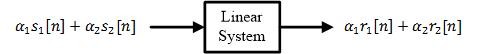
Spectral efficiency R_b/B versus E_b/N_0 determines the overall merit of a modulation scheme. This figure is drawn for BER = 10^{-5} and a Square-Root Raised Cosine pulse with 50% excess bandwidth

Computing Error Rates

Having built a simple digital communication system, it is necessary to know how to measure its performance. As the names say, Symbol Error Rate (SER) and Bit Error Rate (BER) are the probabilities of receiving a symbol and bit in error, respectively. SER and BER can be approximated through simulating a complete digital communication system involving a large number of bits and comparing the ratio of symbols or bits received in error to the total number of bits. Hence, \begin{equation}\label{eqCommSystemSER} \text{SER} = \frac{\text{No. of symbols in error}}{\text{Total no. of transmitted symbols}} \end{equation} and \begin{equation}\label{eqCommSystemBER} \text{BER} = \frac{\text{No. of bits in

Continue reading
A complex number with its I and Q components

Dealing with Complex Numbers

Although complex notation is not complex to understand, I attempt to avoid complex notation altogether while writing DSP articles. If you are interested in where these complex numbers come from, you can read my real-imaginative guide to complex numbers. A complex number is defined as an ordered pair of real numbers in $(x,y)$-plane. In that respect, complex numbers can be considered as vectors with initial point on the origin $(0,0)$. Addition of complex numbers is then similar to the addition of vectors in $(x,y)$-plane from this perspective. However, multiplication is well defined for complex numbers while it is not defined

Continue reading
Minimum distance rule based detector decisions in a QPSK constellation in the presence of a carrier frequency offset

How a Frequency Locked Loop (FLL) Works

We saw before how a carrier frequency offset distorts the received signal. Later, we also described the classification of frequency synchronization techniques according to the availability of the symbol timing. Today, we will learn about the workings of a frequency locked loop. Background A Phase Locked Loop (PLL) is a device used to synchronize a periodic waveform with a reference periodic waveform. It is an automatic control system in which the phase of the output signal is locked to the phase of the input reference signal. In the article referred above, we also discussed that for a very small frequency

Continue reading