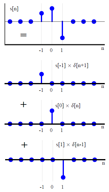
Universe

What is a Signal?

In traditional Digital Signal Processing (DSP) courses, we usually learn about signals in a narrow context. While this is probably the correct approach for an introduction to this field, there is a broader theme to the concept of signals. Let us focus on the purely technical part first. A signal is any measurable quantity that varies with time (or some other independent variable). If you record the words you speak in a computer memory and plot against time, you get a speech signal. As an example, the figure below shows a signal for the words "Hello Wireless" recorded in a computer. Some familiar signals from everyday life are temperature or pressure readings, GPS signals that determine your vehicle’s position, biological

Continue reading
Illustration of peak ISI and asymmetry about -3dB point

Pulse Shaping Filter

In digital logic, a stream of 1s and 0s forms a sequence of rectangular pulses, which can be easily identified at the receiver side by a threshold. In time domain, everything looks nice and perfect. Let us investigate the system characteristics in frequency domain. In a Pulse Amplitude Modulation (PAM) system, the main component that defines the spectral contents of the signal is the pulse shape $p(nT_S)$ at the Tx. We start with our attention towards a simple rectangular pulse shape. Here is a brief outline of what we cover in this article. Table of Contents 1. Spectrum of a Rectangular Pulse 2. Reducing the bandwidth 3. Coefficients of an Ideal Pulse Auto-correlation 4. Raised Cosine (RC) Filter 5. Resulting

Continue reading
Spectral efficiency R_b/B versus E_b/N_0 determines the overall merit of a modulation scheme. This figure is drawn for BER = 10^{-5} and a Square-Root Raised Cosine pulse with 50% excess bandwidth

Computing Error Rates

Having built a simple digital communication system, it is necessary to know how to measure its performance. As the names say, Symbol Error Rate (SER) and Bit Error Rate (BER) are the probabilities of receiving a symbol and bit in error, respectively. SER and BER can be approximated through simulating a complete digital communication system involving a large number of bits and comparing the ratio of symbols or bits received in error to the total number of bits. Hence, \begin{equation}\label{eqCommSystemSER} \text{SER} = \frac{\text{No. of symbols in error}}{\text{Total no. of transmitted symbols}} \end{equation} and \begin{equation}\label{eqCommSystemBER} \text{BER} = \frac{\text{No. of bits in error}}{\text{Total no. of transmitted bits}} \end{equation} Till now, the only imperfection between Tx and Rx entities we have covered is

Continue reading
A complex number with its I and Q components

Dealing with Complex Numbers

Although complex notation is not complex to understand, I attempt to avoid complex notation altogether while writing DSP articles. If you are interested in where these complex numbers come from, you can read my real-imaginative guide to complex numbers. A complex number is defined as an ordered pair of real numbers in $(x,y)$-plane. In that respect, complex numbers can be considered as vectors with initial point on the origin $(0,0)$. Addition of complex numbers is then similar to the addition of vectors in $(x,y)$-plane from this perspective. However, multiplication is well defined for complex numbers while it is not defined for vectors — the dot product of two vectors is a scalar, not a vector, while the cross product of

Continue reading
Minimum distance rule based detector decisions in a QPSK constellation in the presence of a carrier frequency offset

How a Frequency Locked Loop (FLL) Works

We saw before how a carrier frequency offset distorts the received signal. Later, we also described the classification of frequency synchronization techniques according to the availability of the symbol timing. Today, we will learn about the workings of a frequency locked loop. Background A Phase Locked Loop (PLL) is a device used to synchronize a periodic waveform with a reference periodic waveform. It is an automatic control system in which the phase of the output signal is locked to the phase of the input reference signal. In the article referred above, we also discussed that for a very small frequency offset, a PLL is sufficient for driving the phase error between the Rx signal and the local oscillator output to

Continue reading