We have discussed before the effect of a phase offset on the received signal. We have also seen a logical approach to solve this problem as well as one of the earliest algorithms for phase synchronization known as a Costas loop. Here, the purpose is to explain how a Rx detects whether the Phase Locked Loop (PLL) has acquired the lock.
A receiver is simply a blind machine which can implement a PLL but can never get to know how it is actually doing. A lock detector is a logic signal used in the Rx to indicate successful synchronization after which the demodulation process can be started. There are many other uses of a lock detector as follows.
- It helps the Rx in keeping track of a signal loss due to fading and re-acquisition when the signal returns.
- A PLL tends to use different parameters (or even different algorithms in a software defined radio) during acquisition as compared to during tracking.
- A non-data-aided version of an algorithm might be employed during acquisition while a switch to decision-directed mode of the same is made after the lock is achieved.
Therefore, a Rx needs a reliable indication of the lock state for carrier and timing recovery. This is usually implemented through comparing a lock metric with a threshold and forming a hypothesis based on their difference. The averaging over many symbols can be implemented in either a feedforward manner or a feedback fashion while the threshold $\lambda$ is computed based on the minimum tolerable phase offset.
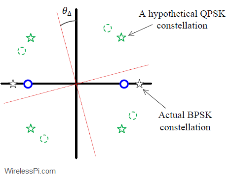
For a BPSK signal, we know that a phase rotation reduces the amplitude in the $I$ arm while injecting this power into the $Q$ arm. A perfectly locked PLL should have all the energy in its $I$ arm, as shown in the figure below.

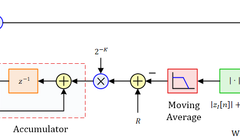
Utilizing this observation, we can construct a carrier lock detector from the matched filter outputs $z(mT_M)$ by taking the difference between $|z_I(mT_M)|$ and $|z_Q(mT_M)|$, averaging it over a long interval and then comparing it against a threshold $\lambda$.
\begin{equation*}
\text{LD}(\theta_\Delta) = \sum \limits _{m=0}^{N_d-1} \Big\{|z_I(mT_M)|-|z_Q(mT_M)| \Big\}
\begin{cases}
\ge \lambda & \quad \text{PLL in lock} \\
\text{otherwise} & \quad\text{PLL unlocked}
\end{cases}
\end{equation*}
This strategy will not work in the case of a QPSK modulation because both $I$ and $Q$ arms contain the signal energy from the modulated symbols. This energy should be equal in the case of a zero $\theta_\Delta$ and hence a zero difference between the two can be taken as an indication of lock. For this purpose, a threshold $\lambda$ close to zero can be chosen.
\begin{equation*}
\text{LD}(\theta_\Delta) = \sum \limits _{m=0}^{N_d-1} \Big\{|z_I(mT_M)|-|z_Q(mT_M)| \Big\}
\begin{cases}
\le \lambda & \quad \text{PLL in lock} \\
\text{otherwise} & \quad\text{PLL unlocked}
\end{cases}
\end{equation*}
Instead of an absolute value, a magnitude squared operation can also be employed. Notice that the above lock detectors operate in a non-data-aided fashion. We can also design their decision-directed counterparts utilizing $\hat a[m]$.
From the above expressions, we realize that the lock detection indicator depends on the signal amplitude because it operates directly on the matched filter outputs. This can cause erroneous lock and unlock flags when the signal power varies. An alternative technique is to divide the lock expressions by the signal magnitude
\begin{equation*}
\sqrt{z^2_I(mT_M)+z^2_Q(mT_M)}
\end{equation*}
that acts as a virtual AGC to normalize the magnitude and deliver an output free of dynamic range problems.