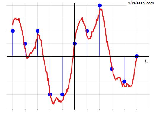
A digital signal and its underlying continuous waveform

Why Digital Communication is Superior to Analog Communication

At the beginning, the history of wireless communication revolved around analog communication systems for several decades. Amplitude Modulation (AM) and Frequency Modulation (FM) were the most widely used techniques during this time. Gradually, however, a transition towards digital transmission occurred in wireless systems as well, a phenomenon that was in sync with digital revolution in the society as a whole. So what are the main benefits of digital technology that made it much superior to its analog counterpart? Let us analyze some of them below [1]. Performance Analog signals suffer from distortion and noise, even if they are small. Although

Continue reading
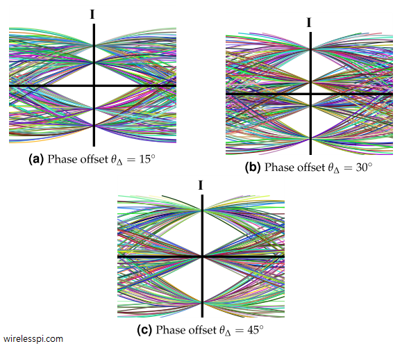
Eye diagrams for I arm of a 4-QAM signal for 15, 30 and 45 degrees phase offsets and a Raised Cosine filter with excess bandwidth 0.5. A similar eye diagram exists for Q arm as well

What is Carrier Phase Offset and How It Affects the Symbol Detection

In case of Quadrature Amplitude Modulation (QAM) and other passband modulation schemes, Rx has no information about carrier phase of the Tx oscillator. Let us explore what impact this has on the demodulation process. Constellation Rotation To see the effect of the carrier phase offset, consider that a transmitted passband signal consists of two PAM waveforms in $I$ and $Q$ arms denoted by $v_I(t)$ and $v_Q(t)$ respectively and combined as \begin{equation}\label{eqRealWorldQAMPhaseOffset} s(t) = v_I(t) \sqrt{2} \cos 2\pi F_C t – v_Q(t) \sqrt{2}\sin 2\pi F_C t \end{equation} Here, $F_C$ is the carrier frequency and $v_I(t)$ and $v_Q(t)$ are the continuous versions

Continue reading
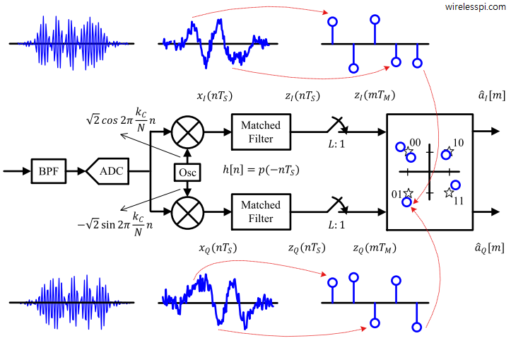
A general QAM detector with respective waveforms at each block

Quadrature Amplitude Modulation (QAM)

Quadrature Amplitude Modulation (QAM) is a spectrally efficient modulation scheme used in most of the high-speed wireless networks today. We discussed earlier that Pulse Amplitude Modulation (PAM) transmits information through amplitude scaling of the pulse $p(nT_S)$ according to the symbol value. To understand QAM, two routes need to be traversed. Route 1 We start the first route with differentiating between baseband and passband signals. A baseband signal has a spectral magnitude that is nonzero only for frequencies around origin ($F=0$) and negligible elsewhere. An example spectral plot for a PAM waveform is shown below for 500 2-PAM symbols shaped by

Continue reading
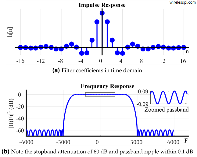
Time and frequency response of a lowpass FIR filter designed with Parks-McClellan algorithm for N=33

Finite Impulse Response (FIR) Filters

We learned in the concept of frequency that most signals of practical interest can be considered as a sum of complex sinusoids oscillating at different frequencies. The amplitudes and phases of these sinusoids shape the frequency contents of that signal and are drawn through magnitude response and phase response, respectively. In DSP, a regular goal is to modify these frequency contents of an input signal to obtain a desired representation at the output. This operation is called filtering and it is the most fundamental function in the whole field of DSP. It is possible to design a system, or filter,

Continue reading
Blocks of a simple binary communication system

A Simple Communication System

"The fundamental problem of communication is that of reproducing at one point either exactly or approximately a message selected at another point." Claude Shannon – A Mathematical Theory of Communication Our main purpose is to transfer digital information – which is a sequence of bits 0’s and 1’s – from one system to another through a communication channel. Let us return for a moment to the concept behind simple digital logic where logic 0 can be assigned to one voltage level while logic 1 to another. Provided the static discipline is followed, all our system electronics has to do is

Continue reading