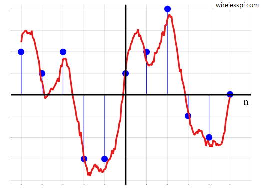
A linear system with scaled input and output

Linear Systems

In wireless communications and other applications of digital signal processing, we often want to modify a generated or acquired signal. A device or algorithm that performs some prescribed operations on an input signal to generate an output signal is called a system. Amplifiers in communication receivers and filters in image processing applications are some systems that we interact with in daily lives. Our main focus in these articles will be on a particular class of systems which are linear and time-invariant. A linear system implies that if two inputs are scaled and summed together to form a new input, the

Continue reading
A digital signal and its underlying continuous waveform

A Digital Signal

We have talked about obtaining a discrete-time signal through sampling the time-axis and obtaining a discrete frequency set through sampling the frequency axis. The same concept can be applied to the amplitude-axis, where the signal amplitude can be sampled to take only a finite set of discrete values. This discrete-time discrete-valued signal is called a digital signal, as opposed to an analog signal that is continuous in time and continuous in amplitude. The above figure shows how a digital signal having amplitudes over a fixed set of values can be obtained through slicing the underlying continuous amplitudes. For example, an

Continue reading

Some DFT Properties

The purpose of this article is to summarize some useful DFT properties in a table. My favorite property is the beautiful symmetry depicted by continuous and discrete Fourier transforms. However, if you feel that this particular content is not as descriptive as the other posts on this website are, you are right. As opposed to the rest of the content on the website, we do not intend to derive all the properties here. Instead, based on what we have learned, some important properties of the DFT are summarized in the table below with an expectation that the reader can derive

Continue reading
The blue line is the signal template and while red is the matched filter. Notice the same magnitude on each spectral line but exactly opposite phase

Demodulation – From Signals Back to Numbers

Remember that in the article on correlation, we discussed that correlation of a signal with proper normalization is maximum with itself and lesser for all other signals. Since the number of possible signals is limited in a digital communication system, we can use the correlation between incoming signal $r(nT_S)$ and possible choices $s_0(nT_S)$ and $s_1(nT_S)$ in a digital receiver. Consequently, a decision can be made in favor of the one with higher correlation. It turns out that the theory of maximum likelihood detection formalizes this conclusion that it is the optimum receiver in terms of minimizing the probability of error.

Continue reading