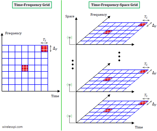
A view of time-frequency-space grid in a communication system

How Multiple Antennas Sample the Signal

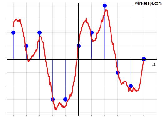
Once upon a time, an antenna was viewed as a simple device to transmit and receive an electromagnetic wave, much like a battery the sole purpose of which is to provide electrical power. A set of antennas, however, can be viewed from a new angle as follows. Sampling in Time Domain An Analog-to-Digital Converter (ADC) is a device that samples an analog signal in time domain to create a corresponding sequence of numbers. Similarly, a Digital-to-Analog Converter (DAC) gets a sequence of numbers as an input to generate a reconstructed analog signal. As an example, a rectangular pulse shape is

Continue reading
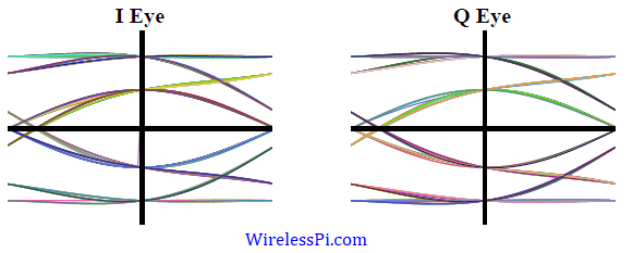
Eye diagram for a 4-QAM modulated signal and a simple channel impulse response

Impact of Multipath on the Received Signal

In this article, we describe the impact of multipath caused by the wireless channel on the signal arriving at the receiver from a constellation viewpoint. Recall that an eye diagram, a transition diagram and a scatter plot are the stethoscopes of a communication system and hence it is imperative to bring in that perspective for a Tx signal convolved with the channel impulse response. This is because a wireless channel can be seen as a Finite Impulse Response (FIR) filter with the result that the sampled Rx signal is a convolution between taps of this FIR filter and the Tx

Continue reading
A digital signal and its underlying continuous waveform

Why Digital Communication is Superior to Analog Communication

At the beginning, the history of wireless communication revolved around analog communication systems for several decades. Amplitude Modulation (AM) and Frequency Modulation (FM) were the most widely used techniques during this time. Gradually, however, a transition towards digital transmission occurred in wireless systems as well, a phenomenon that was in sync with digital revolution in the society as a whole. So what are the main benefits of digital technology that made it much superior to its analog counterpart? Let us analyze some of them below [1]. Performance Analog signals suffer from distortion and noise, even if they are small. Although

Continue reading
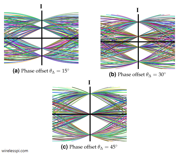
Eye diagrams for I arm of a 4-QAM signal for 15, 30 and 45 degrees phase offsets and a Raised Cosine filter with excess bandwidth 0.5. A similar eye diagram exists for Q arm as well

What is Carrier Phase Offset and How It Affects the Symbol Detection

In case of Quadrature Amplitude Modulation (QAM) and other passband modulation schemes, Rx has no information about carrier phase of the Tx oscillator. Let us explore what impact this has on the demodulation process. Constellation Rotation To see the effect of the carrier phase offset, consider that a transmitted passband signal consists of two PAM waveforms in $I$ and $Q$ arms denoted by $v_I(t)$ and $v_Q(t)$ respectively and combined as \begin{equation}\label{eqRealWorldQAMPhaseOffset} s(t) = v_I(t) \sqrt{2} \cos 2\pi F_C t – v_Q(t) \sqrt{2}\sin 2\pi F_C t \end{equation} Here, $F_C$ is the carrier frequency and $v_I(t)$ and $v_Q(t)$ are the continuous versions

Continue reading
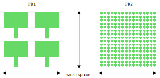
For the same area and their spacing (with respect to the wavelength), the number of elements in the array at high band is larger thus capturing a similar or increased amount of power

Free Space Propagation in mmWave Systems

In this article, we describe the free space propagation in mmWave systems. During the discussion, we dispel a common myth that the received power at any distance decays with increasing carrier frequency. We will see that the received power is in fact independent of the carrier frequency for suitably designed systems such as those at mmWave frequencies. Instead, it is only after including the atmospheric effects such as water vapors, oxygen, rain and penetration loss in materials that the carrier frequency plays a substantial role in establishing the link budget. Suppose that a Tx transmits $P_{\text{Tx}}$ watts of power uniformly

Continue reading