Wired and wireless channels

Modulation – From Numbers to Signals

The purpose of digital communications is to send digital data across a channel which can be wireless telephone lines coaxial cable optical fiber Ethernet USB chips on a printed circuit board Considering the examples shown in Figure above, clearly neither a bit sequence nor a symbol sequence can be transmitted on their own through these channels — as they are nothing more than a set of numbers. Therefore, a signal waveform is an appropriate tool that can travel down the channel and carry the required information — just like a train running on its track and carrying the load. For

Continue reading
An illustration of wiping off the modulation process without any training information

Non-Data-Aided Carrier Phase Estimation

A carrier phase offset rotates the Rx constellation causing decision errors even in a perfectly noiseless environment. One of the techniques used to overcome this problem is to insert a known sequence at the start of the transmission known as a preamble. Then, the Rx can utilize these known symbols in the arriving signal to estimate the carrier phase and de-rotate the constellation. However, inserting a known sequence within the message decreases the spectral efficiency of the system. To avoid this cost, a phase estimator (as well as estimators for other distortions) can be derived in a non-data-aided fashion. One

Continue reading
Square-Root Raised Cosine (SR-RC) spectrum with different excess bandwidths

Modulation Bandwidths

From the article on pulse shaping, we can correctly determine the occupied bandwidth for each modulation scheme where the Square-Root Raised Cosine spectrum shows the bandwidth of a Square-Root Raised Cosine pulse shape as $0.5(1+\alpha)R_M$. Also, we have discussed earlier that the spectrum approximately remains the same, provided that there is enough randomness in bit stream and the resulting symbols are equally likely and independent from each other. Therefore, the bandwidth for a PAM modulated signal can be given as \begin{equation}\label{eqCommSystemBWPAM} BW_{\text{PAM}} = 0.5\left(1+\alpha\right)R_M \end{equation} QAM is basically a similar modulation scheme except that it is modulated on a carrier.

Continue reading
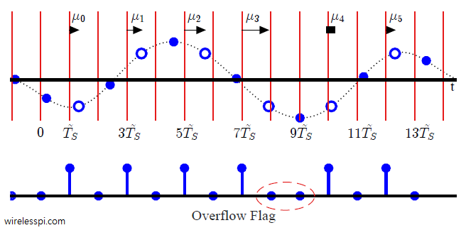
A Phase Locked Loop (PLL) for digital symbol timing recovery

Phase Locked Loop (PLL) for Symbol Timing Recovery

A Phase Locked Loop (PLL) is a device used to synchronize a periodic waveform with a reference periodic waveform. It is an automatic control system in which the phase of the output signal is locked to the phase of the input reference signal. In the context of carrier phase synchronization, we talk about tracking the phase of an input reference sinusoid. For carrier frequency synchronization, a Frequency Locked Loop (FLL) is implemented. For the purpose of timing synchronization, the target is to adjust the timing phase of a receiver clock to that of the transmitter clock such that one sample/symbol

Continue reading
A channel with 8 taps demonstrating the main cursor, precursor ISI and postcursor ISI

How Decision Feedback Equalizers (DFE) Work

We started the classification of equalization algorithms by introducing the need for equalization in wireless communication systems. We said that the wireless channel is a source of severe distortion in the received (Rx) signal and our main task is to remove the resulting Inter-Symbol Interference (ISI) from the Rx samples. Equalization refers to any signal processing technique in general and filtering in particular that is designed to eliminate or reduce this ISI before symbol detection. In essence, the output of an equalizer should be a Nyquist pulse for a single symbol case. A conceptual block diagram of the equalization process

Continue reading