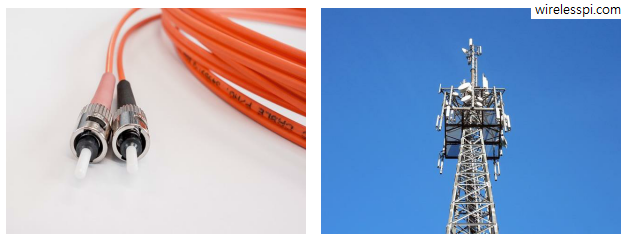
In the article on modulation – from numbers to signals, we said that the Pulse Amplitude Modulation (PAM) is an amplitude scaling of the pulse $p(nT_S)$ according to the symbol value. What happens when this process of scaling the pulse amplitude by symbols is repeated for every symbol during each interval $T_M$? Clearly, a series of bits $b$ (1010 in our initial example) can be transmitted by choosing a rectangular pulse and scaling it with appropriate symbols. \begin{equation*} \begin{aligned} m = 0 \quad b = 1 \quad a[0] = +A \\ m = 1 \quad b = 0 \quad a[1]
Continue readingCategory: Wireless/SDR
Wireless communications and Software Defined Radio (SDR)
How to Detect a Carrier Lock in an SDR
We have discussed before the effect of a phase offset on the received signal. We have also seen a logical approach to solve this problem as well as one of the earliest algorithms for phase synchronization known as a Costas loop. Here, the purpose is to explain how a Rx detects whether the Phase Locked Loop (PLL) has acquired the lock. A receiver is simply a blind machine which can implement a PLL but can never get to know how it is actually doing. A lock detector is a logic signal used in the Rx to indicate successful synchronization after
Continue readingDemodulation – From Signals Back to Numbers
Remember that in the article on correlation, we discussed that correlation of a signal with proper normalization is maximum with itself and lesser for all other signals. Since the number of possible signals is limited in a digital communication system, we can use the correlation between incoming signal $r(nT_S)$ and possible choices $s_0(nT_S)$ and $s_1(nT_S)$ in a digital receiver. Consequently, a decision can be made in favor of the one with higher correlation. It turns out that the theory of maximum likelihood detection formalizes this conclusion that it is the optimum receiver in terms of minimizing the probability of error.
Continue readingDigital Filter and Square Timing Recovery
We have seen before how a symbol timing offset severely impacts the constellation of the received symbols. Therefore, symbol timing recovery is one of the most crucial jobs of a digital communications receiver. In the days of analog clock recovery, a timing error detector provided the instant to sample the Rx waveform at 1 sample/symbol at the maximum eye opening. However, discrete-time processing opened the doors for better timing recovery schemes as an ever increasing number of transistors within the same area consistently keeps bringing the digital processing cost down. Consequently, the use of analog circuits to control the timing
Continue readingConvoluted Correlation between Matched Filter and Correlator
Now we turn out attention towards a topic that causes a lot of confusion for communications and DSP learners: what is the difference between a matched filter and a correlator in a communications receiver? Let us start with the definition of a correlator: A correlator is a device that performs correlation of a received signal with its template within a given window of time. In our context, that window of time is the symbol duration, $T_M$. So a correlator performs the following operations. It takes this sample-by-sample product and sums them together. Next, it samples the output of this accumulation
Continue reading