The tasks of a communications receiver to demodulate the transmitted signal begin with selecting the signal within a specific bandwidth at a desired frequency, commonly known as a particular channel. In another article, we discuss specifications for a radio receiver such as dynamic range, noise floor and sensitivity. Today we discuss an architecture used in earlier generations of radios.
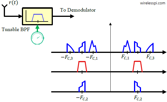
To avoid interference from the neighboring channels, the most straightforward approach is to filter out the spectral contents outside this channel and amplify the desired signal in one or more RF amplification stages. This was one of the earliest techniques employed for building radio receivers known as Tuned Radio Frequency (TRF) systems and consists of an adjustable, or tunable, Bandpass Filter (BPF) around the desired frequency. From a signal processing viewpoint, the main idea is to move the filter to the signal.
For example, the signal at frequency $F_{C,2}$ is selected through tuning the bandpass filter to frequency $F_{C,2}$ that removes all other spectral contents, as illustrated in the figure below. If an adjacent channel were to be chosen, the tuning control mechanism consisting of circuit elements like variable capacitors and inductors just altered the center frequency of this filter. The major problem with a TRF is designing tunable bandpass filter with constant bandwidth and sufficient frequency selectivity over the entire tunable range.

A typical TRF radio consists of multiple stages, each tuned to a specific frequency that operates in the following manner:
- Tuning: In a TRF receiver, multiple stages of amplification are used, with each stage tuned to a specific frequency using adjustable tuned circuits, which are typically LC circuits. The reason for cascading multiple stages is to provide greater selectivity.
- Amplification: The incoming radio signal is received through an antenna and fed into the first tuned stage. The signal is amplified to overcome losses in different stages of processing.
- Selectivity: The tuned stages are carefully adjusted so that they amplify signals only within a narrow frequency range (as explained above), providing high selectivity. This means that the receiver can focus on a specific frequency while rejecting others to reduce the interference.
- Detection: After passing through the tuned stages, the signal is detected and demodulated to recover the original audio or data signal. This detection can be accomplished using various methods, such as envelope detection or superheterodyne conversion.
- Audio Output: Once the signal is demodulated, the audio information is passed to the output stage for conversion into audible sound.
Suffering from poor selectivity and low sensitivity, TRF receivers quickly became obsolete within the early years of radio and gave way to superheterodyne and direct conversion receivers. In today’s age of fast digital electronics, there would have been no need to even mention them as a category for Rx architectures. Surprisingly, however, they do have a reincarnation in the realm of digital signal processing where it is straightforward to move the filter to the channel through appropriate conversion of a lowpass filter to a bandpass filter.


