During World War I, Edwin Howard Armstrong invented the superheterodyne Rx as an alternative to the Tuned Radio Frequency (TRF) receivers that moved a tunable filter to the desired signal. His purpose was to overcome their limitations in regard to selectivity and sensitivity. To understand the principle of a heterodyne receiver, a pictorial representation is of utmost importance. While this is generally true for all concepts, there are specific issues of spectral translations in receiver architectures that require nice and clear figures. This is how I proceed below.
The Heterodyne Principle
Instead of employing a tunable bandpass filter that is shifted to the signal frequency, the concept of a heterodyne Rx is to design a tunable Local Oscillator (LO) operating at $F_{\text{LO}}$ that moves the signal to a fixed bandpass filter, as drawn in the figure below. This filter operates at an explicit frequency known as an Intermediate Frequency (IF).

So what exactly have we gained here?
The advantage of such an approach is that regardless of the selected channel, most of the amplification and filtering operations are performed at the fixed intermediate frequency where it is relatively easier to design high gain amplifiers and filters exhibiting sharp transition bandwidths.
We now understand this idea through the signal and interference spectra.
Upconversion at Tx Side
The starting point is the spectrum of a real sinusoid $\cos 2\pi F_C t$ at a carrier frequency $F_C$. This spectrum consists of two impulses, one at $+F_C$ and the other at $-F_C$ as explained here. At the Tx, this sinusoid is mixed (i.e., multiplied) with the modulated signal $v(t)$ as
\begin{equation*}
s(t) = v(t)\cdot \cos 2\pi F_C t
\end{equation*}
The spectrum of the modulated signal $v(t)$ is denoted as $V(F)$. Now time domain multiplication is frequency domain convolution. Therefore, in frequency domain, a convolution takes place between those two spectral impulses (arising from the cosine) and the spectrum $V(F)$ of the modulated signal. This convolution results in $V(F)$ shifted to two frequencies, namely $\pm F_C$, thus producing the passband signal $S(F)$.
\begin{equation*}
S(F) = \frac{1}{2} \left[S(F+F_C) + S(F-F_C)\right]
\end{equation*}
This resulting signal is drawn in the first row of the figure below.

Let us explore what happens at the Rx side.
Downconversion at Rx Side
At the Rx side, $S(F)$ is mixed with a tunable LO with a sinusoid $\cos 2\pi F_{\text{LO}} t$ at frequency $F_{\text{LO}}$.
\begin{equation*}
x(t) = s(t)\cdot \cos 2\pi F_{\text{LO}} t = v(t) \cdot \cos 2\pi F_C t \cdot \cos 2\pi F_{\text{LO}} t
\end{equation*}
Using the identity $2\cos A\cos B$ $=$ $\cos (A+B)$ $+$ $\cos (A-B)$, these two resulting real sinusoids at the Rx in time domain imply four impulses in frequency domain. The convolution occurs again, this time generating the copies of $V(F)$ at the following four frequencies.
\begin{equation}
\begin{aligned} \label{eqNoTitleFCflo}
+F_C +F_{\text{LO}} &\qquad -F_C -F_{\text{LO}}\\
+F_C -F_{\text{LO}} &\qquad -F_C +F_{\text{LO}}
\end{aligned}
\end{equation}
This principle of spectral translations through convolution with $F_{\text{LO}}$ is plotted in the figure above. Since the bandpass filter at the Rx is located at the Intermediate Frequency (IF), one of the above spectral replicas must fall at the same frequency. Assuming that this copy is $F_C-F_{\text{LO}}$ out of the four shown in this figure, the signal is downconverted to an IF equal to
\begin{equation*}
F_{\text{IF}} = +F_C – F_{\text{LO}}
\end{equation*}
For a fixed $F_{\text{IF}}$ and variable $F_{\text{LO}}$, we can capture any channel by tuning $F_{\text{LO}}$ according to the above relation.
F_{\text{LO}} = F_C -F_{\text{IF}}
\end{equation}
Since $F_{\text{LO}}$ $<$ $F_C$, this kind of mixing is known as low side injection. The other option is high side injection in which $F_{\text{LO}}$ $>$ $F_C$. Next, we investigate the image frequency problem in a heterodyne Rx.
The Image Frequency
While explaining the superheterodyne principle in the above figure, we made an assumption that the whole spectrum only consists of our desired signal. In reality, the very concept of a spectrum is based on dividing the users in frequency domain by assigning them different frequencies, commonly known as Frequency Division Multiplexing (FDM). For this reason, much of the empty spectrum here is actually occupied by other transmissions.
This fact proves harmful for a Rx working with real sinusoids due to the following reason.
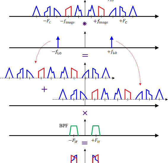
- Our spectral translation brings the desired signal $s(t)$ at carrier frequency $F_C$ into the passband of the filter at intermediate frequency $F_{\text{IF}}$. As plotted in the figure below, this is through convolution with the impulse at $-F_{\text{LO}}$.
- The same translation also brings another spectrum to $F_{\text{IF}}$ due to the convolution with the impulse at $F_{\text{LO}}$. From inspection of this figure, it becomes clear that the spectrum interfering with the desired signal comes from a frequency located $F_{\text{IF}}$ away from $F_{\text{LO}}$. To understand this point, measure the frequency difference between $F_C$ and $F_{\text{LO}}$, and then between $F_{\text{LO}}$ and $F_{\text{image}}$ in the above figure.

The above fact helps us in calculating the location of the image frequency $F_{\text{image}}$ for low side injection as
F_{\text{image}} = F_C -2F_{\text{IF}}
\end{equation}
Intuitively, this relation makes sense because keeping in mind the addition and subtraction of the sinusoidal frequencies, $F_{\text{IF}}$ is reached from one side by the signal at $F_C$ and from the other side by a signal that is at a further frequency difference of $F_{\text{IF}}$, as shown at the top of the above figure. Once the image frequency is in the mixer, there is no way to remove it since it is now heterodyned into the same IF band as the desired station.
The Superheterodyne Architecture
A superheterodyne Rx solves the image frequency issue by inserting an Image Reject (IR) filter prior to the mixer. This leads to a superheterodyne Rx architecture drawn in the figure below.

A superheterodyne receiver works in the following stages.
- An RF preselection filter serves the purpose of removing out of band signal energy as well as partially suppressing the signal located at the image frequency.
- The signal is subsequently amplified by a Low Noise Amplifier (LNA).
- Next, the image frequency signal is cleaned up by an Image Reject (IR) filter. Whether the IR filter is fixed or tunable depends on the band of desired signals that determines where the image frequencies are located. In any case, the requirements on an IR filter are much relaxer than the TRF Rx since its only purpose is to filter out the image signal (as opposed to filtering out everything around the desired band) and the image frequencies lie away from the center frequency. This results in a large transition bandwidth and low cost for the IR filter.
- The signal at the IR filter output is multiplied or mixed with the output of a tunable Local Oscillator (LO) to downconvert the desired band to a fixed Intermediate Frequency (IF).
- Eventually the output can be shifted directly to baseband from here or further downconverted to lower IFs before final demodulation. If another stage of downconversion is utilized, such an architecture is known as a dual-IF receiver.
At this stage, it is imperative to have a look at the output signals at various stages during this process to get an insight into the design of an IR filter. This is illustrated in the figure below in which the difference between the transition bands of the IR filter and the fixed BPF is of particular note.

We have seen in Eq (\ref{eqNoTitleFimage}) that the desired signal and the image signal are separated by twice the IF.
- Recalling that a larger transition bandwidth puts relaxer constraints on a filter, it is attractive to choose a high IF so that the frequency spacing between the desired signal and the image signal is as large as possible. This is shown by the top arrows and a wide IR filter in the above figure.
- On the other hand, a low IF allows utilization of high-quality channel select filters with better selectivity or out-of-band rejection.
Consequently, the choice of IF depends on the tradeoff between image rejection and channel selection qualities. Since the image falls directly over the intended channel, it deteriorates the sensitivity of the Rx. This then translates into the more familiar sensitivity-selectivity tradeoff in a communication receiver.
Over the years, a heterodyne architecture has been widely used in communication receivers due to its good performance achieved by striking a balance in the tradeoffs mentioned above. Nevertheless, it requires more external (to the integrated chip) components due to multiple conversion stages and consequently occupies a larger form factor. As a consequence, the trend has been to shift towards other architectures with less analog and more digital signal processing load such as direct conversion (zero-IF), low-IF and direct sampling receivers. You might also enjoy the description of Cascade Integrator Comb (CIC) filters and how they accomplish the task of sample rate conversion with minimal resources in digital frontends of transmitters and receivers, or how a Direct Digital Synthesizer (DDS) generates a desired waveform through discrete-time techniques.
So what’s the meaning of the “Super” of “Superheterodyne”?I once read an article in which the “Super” is “supersonic”.But in your article,you said that the difference between “heterodyne” and “Superheterodyne” is Image Reject (IR) filter.I am a little confused.I’m looking forward to your reply.
Heterodyne is basically frequency conversion. The term ‘super’ was included to indicate superior performance and has no technical connotation.
Howdy.
There is a notion that super- means upper injection of the Local Oscillator frequency. Lower injection is referred to a sub-heterodyne.
Cheers.
Thank you for the information.