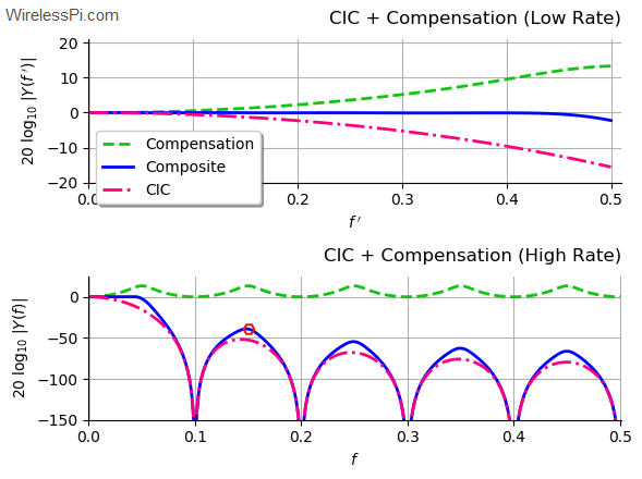
Spectrum of the cascade of CIC filters with a wideband compensation filter for rate change factor 10, unit differential delay and 4 stages

Cascaded Integrator Comb (CIC) Filters – A Staircase of DSP

In olden days, people used to have lots of kids. A famous Urdu satirist once wrote: "It has been observed that the last kid is usually the most mischievous of them all. Therefore, there should be no last kid in a family!" I remembered this line today because I have observed that starting a write-up is the most difficult task of them all. Therefore, there is no introductory paragraph in this article. Suffice it to say that this is the only topic I have found that takes you from a very small first step (just two additions) to really advanced

Continue reading
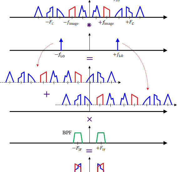
The image frequency problem of a superheterodyne Rx

The Heterodyne Principle and the Superheterodyne Receiver

During World War I, Edwin Howard Armstrong invented the superheterodyne Rx as an alternative to the Tuned Radio Frequency (TRF) receivers that moved a tunable filter to the desired signal. His purpose was to overcome their limitations in regard to selectivity and sensitivity. To understand the principle of a heterodyne receiver, a pictorial representation is of utmost importance. While this is generally true for all concepts, there are specific issues of spectral translations in receiver architectures that require nice and clear figures. This is how I proceed below. The Heterodyne Principle Instead of employing a tunable bandpass filter that is

Continue reading
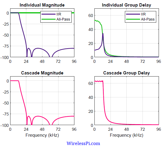
Individual and cascade frequency responses as well as group delays of the IIR and all-pass filters combination

FIR vs IIR Filters – A Practical Comparison

When it comes to practical applications, digital filter design is one of the most important topics in digital signal processing. Today we discuss a critical question encountered in filter design: how to compare the Finite Impulse Response (FIR) and Infinite Impulse Response (IIR) filters. Since there is no clear winner, answering this question enables a designer to choose the right solution for their product. A brief comparison of FIR vs IIR filters is now explained below. Computational Complexity It is well known that most practical signals are simply sums of sinusoids. This implies that signals with sharp transition in time

Continue reading
An atom and the solar system

Sampling and the Mysterious Scaling Factor

This post treats the signals in continuous time which is different than the approach I adopted in my book. The book deals exclusively in discrete time. Some time ago, I came across an interesting problem. In the explanation of sampling process, a representation of impulse sampling shown in Figure below is illustrated in almost every textbook on DSP and communications. The question is: how is it possible that during sampling, the frequency axis gets scaled by $1/Ts$ — a very large number? For an ADC operating at 10 MHz for example, the amplitude of the desired spectrum and spectral replicas

Continue reading
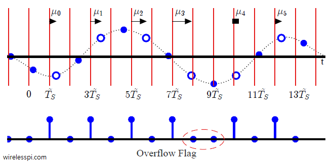
Due to a Sampling Clock Offset (SCO), a fast Rx clock collects extra samples

Effect of Sampling Clock Offset on a Single-Carrier Waveform

We have discussed before the distortion caused by a symbol timing offset on the communication waveform. We have also derived a maximum likelihood estimate of the clock phase offset. In this article, we describe the impact of a sampling clock offset in a single-carrier waveform, also commonly known as a clock frequency offset or timing drift. A clock frequency offset is defined as the rate mismatch between the Tx and Rx clocks. Just like a carrier phase and frequency offset, the clock used to sample the incoming continuous-time signal at a rate $T_S=1/F_S$ contains a phase and frequency offset as

Continue reading