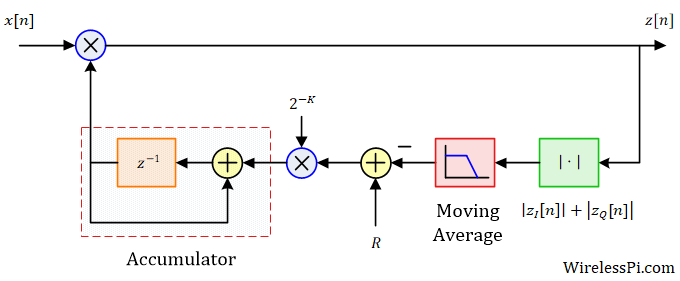
Feedback AGC block diagram

How Automatic Gain Control (AGC) Works

Alfred North Whitehead said, "Civilization advances by extending the number of important operations which we can perform without thinking of them." In today’s world, it is easy to take no notice of the level of process automation integrated into our lives. To have an idea of how things were in the early days, signal processing technology to sort out the radar picture on a map was not available and only a dot or a line could be generated on the screen representing a detected target. A radar operator had to stare at a screen for their whole shift to raise

Continue reading
A figurative example of IQ imbalance depicting potential sources of mismatches

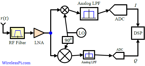
Direct Conversion (Zero-IF) Receiver

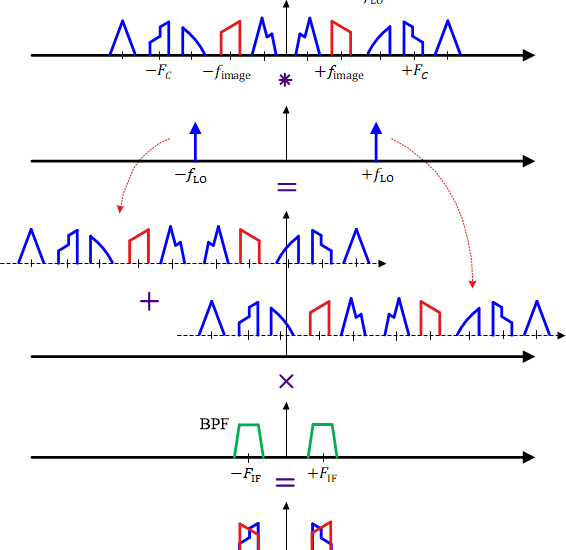
The frontend of the transceiver plays a crucial role in determining the ultimate system performance. In a previous article, we described how a superheterodyne architecture helps in enhancing the selectivity and sensitivity of the receiver. Some of the main issues with a superheterydone receiver are the image frequency and a large form factor due to multiple conversion stages. Today we discuss a direct conversion architecture, also known as zero-IF and homodyne. Recall from the concept of frequency domain that a real sinusoid at the Local Oscillator (LO) output has two impulses in its spectrum, one at a positive frequency $+F_{\text{LO}}$

Continue reading
The image frequency problem of a superheterodyne Rx

The Heterodyne Principle and the Superheterodyne Receiver

During World War I, Edwin Howard Armstrong invented the superheterodyne Rx as an alternative to the Tuned Radio Frequency (TRF) receivers that moved a tunable filter to the desired signal. His purpose was to overcome their limitations in regard to selectivity and sensitivity. To understand the principle of a heterodyne receiver, a pictorial representation is of utmost importance. While this is generally true for all concepts, there are specific issues of spectral translations in receiver architectures that require nice and clear figures. This is how I proceed below. The Heterodyne Principle Instead of employing a tunable bandpass filter that is

Continue reading
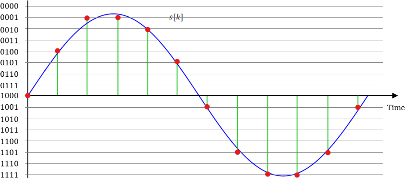
Pulse Code Modulation (PCM)

Specifications of a Radio Receiver

When designing a radio receiver, a system architect has to deal with the issues such as dynamic range, noise floor and sensitivity of a radio receiver [1]. The ultimate purpose is computing a power budget to ensure that a minimum amount of signal power is available at the receiver during operation. This is not much different than how a country assigns an available budget into different sectors such as defense, education and health. Dynamic Range Dynamic range is the ratio of the largest signal level to the smallest signal level that the system can process in analog and digital stages.

Continue reading
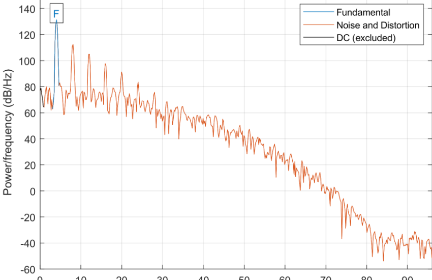
SINAD for signal, noise and distortion

How to Compute SINAD in a Radio Receiver

In theory, the quantity that determines the performance of a radio receiver is the Signal to Noise Ratio (SNR). In linear terms, this is simply the ratio of the signal power versus the noise power appearing at the demodulator input. \[ SNR = 10\log_{10} \frac{P_S}{P_N} \] where $P_S$ is the signal power and $P_N$ is the noise power within the spectrum. However, when experimental measurements are carried out in order to verify the theoretical conclusions, SNR alone is not enough and there is another quantity, known as SINAD, that governs the receiver performance. What is SINAD SINAD stands for Signal

Continue reading