In theory, the quantity that determines the performance of a radio receiver is the Signal to Noise Ratio (SNR). In linear terms, this is simply the ratio of the signal power versus the noise power appearing at the demodulator input.
\[
SNR = 10\log_{10} \frac{P_S}{P_N}
\]
where $P_S$ is the signal power and $P_N$ is the noise power within the spectrum. However, when experimental measurements are carried out in order to verify the theoretical conclusions, SNR alone is not enough and there is another quantity, known as SINAD, that governs the receiver performance.
What is SINAD
SINAD stands for Signal to Noise and Distortion ratio at an analog receiver.
\[
\text{SINAD} = 10\log_{10} \frac{P_S+P_N+P_D}{P_N+P_D}
\]
where $P_D$ is the power in distortion components present within the spectrum, often in the form of harmonics. Harmonics are the replicas of the signal appearing at integer multiples of the signal frequency. As an example, harmonics of a 4 kHz signal appear at 8 kHz, 12 kHz, and so on. Due to the manner in which it is defined here, the power ratio in a SINAD measurement is always greater than 1 (and hence positive in dB).
Measurement Procedure in an Analog Receiver
Taking the case of an FM receiver, the primary task is to measure the numerator and denominator of the above equation. In this regard, a common technique is to transmit a 1 kHz FM signal with given specifications (e.g., 3 kHz frequency deviation).
- The receiver measures the signal power level that contains the desired signal, noise and distortion components that form the numerator in the above expression.
- In a parallel path, it is also passed through an analog notch filter that eliminates the signal component thus leaving only noise and distortion. A power measurement of this output forms the denominator of the above expression.
Finally, the ratio of these two quantities is the SINAD value.
The next question is how SINAD is related to the receiver sensitivity. Remember that the sensitivity quantifies the weakest radio frequency signal a device can reliably demodulate. To fix an objective indicator of reliable demodulation, a SINAD value of 12 dB is chosen as the standard. What this means is that the input voltage level is started at a low value in the testing procedure and then raised in a gradual manner until a SINAD value of 12 dB is produced at the output. The voltage level resulting in this SINAD is characterized as the receiver sensitivity in dBm or $\mu$V. This procedure helps compare the performance of receivers from different manufacturers. In addition to sensitivity, SINAD is also useful in measuring other performance metrics like blocker analysis and adjacent channel rejection.
Measurement Procedure in a Digital Receiver
In a digital receiver, the main performance metric is the Bit Error Rate (BER). Here, the RF signal level that results in 5% BER determines the receiver sensitivity. A SINAD measurement is not useless though and helps establish the dynamic performance of an Analog-to-Digital Converter (ADC). It is the Signal to Noise and Distortion ratio that an ADC presents at the input of the Digital Signal Processing (DSP) chain.
\[
\text{SINAD} = 10\log_{10} \frac{P_S}{P_N+P_D}
\]
In this scenario, the power ratios in the SINAD measurement can be greater or less than 1 (and hence positive and negative readings in dB, respectively).
As opposed to designing an analog notch filter described above, processing the samples in digital domain is a straightforward task through using an $N$-point Fast Fourier Transform (FFT). The width of each frequency bin is $f_s/N$ where $f_s$ is the signal sampling rate. Just like an analog spectrum analyzer, the FFT output measures the amplitudes of the desired signal as well as the harmonics and noise. This can achieved by simply accounting for the relevant bins in the calculation and the process is repeated for various input frequencies.
Computing SINAD in Matlab
Matlab provides a function sinad() for a convenient implementation that computes a periodogram using a Kaiser window with the parameter $\beta=38$ and excludes the DC component from the calculation. More accurate results can be obtained by using a better window. A code sample with Blackman Harris window is given below where $x$ is the input signal
lenx = length(x);
[psdx, fx] = periodogram( x, blackman(lenx), lenx, fs);
sinad(psdx, fx, ‘psd’);
Using this function, an example of of a scenario in which only the desired signal and noise are present is plotted in the figure below. A high SINAD measurement is displayed at the top of the figure.

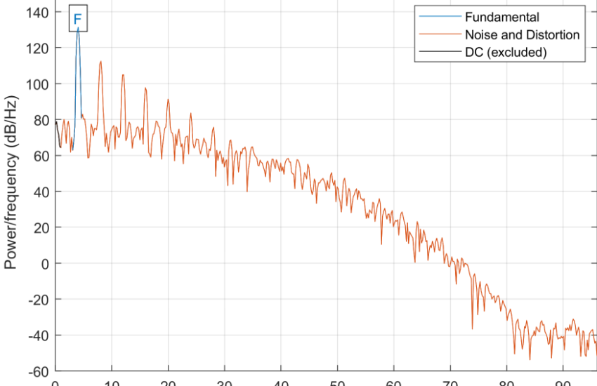
On the other hand, when the harmonic distortion is also present in the signal, the SINAD is considerably reduced. This is shown for a 4 kHz signal whose harmonics are present at its integer multiples such as 8 kHz, 12 kHz, 16 kHz and so on.

References
[1] W. Kester, Understand SINAD, ENOB, SNR, THD, THD + N, and SFDR so You Don’t Get Lost in the Noise Floor, Analog Devices Tutorial MT-003.