An intuitive way to understand the maximum ratio transmission

Maximum Ratio Transmission (MRT)

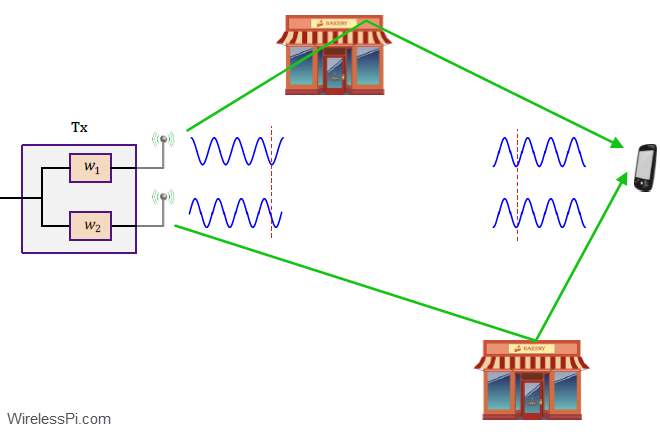
In Maximum Ratio Combination (MRC), our focus was on combining the signals from multiple antennas at the Rx side. Here, we will see how a similar system can be developed with multiple antennas at the Tx side. As our first consideration, we attempt to replicate the results of Rx diversity in a scenario where there are multiple Tx antennas and a single Rx antenna. This is commonly known as a Multiple-Input Single Output (MISO) system. Assume that there are $N_T$ Tx antennas available and only a single Rx antenna as shown in the figure below. This is a dual problem

Continue reading
Maximum Ratio Combining (MRC) cancels the phase and grades the magnitudes according to each channel gain

Maximum Ratio Combining (MRC)

In the discussion on diversity, we described in detail the idea of space diversity through an example of Selection Combining (SC). Maximum Ratio Combining (MRC) is another space diversity scheme that embodies the concept behind generalized beamforming — the main technology in 5G cellular systems. Let us find out how. Setup Consider a wireless link with 2 Tx antenna and 2 (or more) Rx antennas as shown in the figure below. At each symbol time, a data symbol $s$ is transmitted which belongs to a Quadrature Amplitude Modulation (QAM) scheme. To focus on the events happening within one symbol time

Continue reading
Beamforming in multi-user vs massive MIMO systems

Zero-Forcing (ZF) Detection in Massive MIMO Systems

Massive MIMO is one of the defining technologies in 5G cellular systems. In a previous article, we have described spatial matched filtering (or maximum ratio) as the simplest algorithm for signal detection. Here, we explain another linear technique, known as Zero-Forcing (ZF), for this purpose. It was described before in the context of simple MIMO systems here. Background Consider the block diagram for uplink of a massive MIMO system as drawn below with $N_B$ base station antennas and $K$ mobiler terminals. It is evident that the cumulative signal at each base station antenna $j$ is a summation of signals arriving

Continue reading

Antenna Arrays: Whole is More than its Parts

In a previous article, we described how multiples antennas can be viewed as sampling the signal in space domain in a direct analogy to sampling the signal in time domain. Filters in discrete-time domain are usually defined by numerical values in the time axis. Space allows three-dimensional freedom. A filter in discrete space can have its elements placed anywhere in the space. This sounds very complicated! But we will show it is not. A Simple Time Domain Filter: 2-Tap FIR The simplest discrete FIR filter has only two samples of unit magnitude. Assuming unit magnitude and zero phase for both

Continue reading
A beam formation process can be seen in water waves by throwing two stones

Beamforming – Mindfulness of an Antenna Array

If beamforming has to be explained in the most succinct manner, it is the mindfulness of an antenna array where it focuses its attention towards one specific location (or a few specific locations). We find out in this article how it is achieved. As opposed to its reputation, beamforming is not a mysterious technology. It has been used by signal processing engineers for radio applications since long. For example, Marconi used four antennas to increase the gain of signal transmissions across the Atlantic in 1901. It has also been known since 1970s that multiple antennas at the base station help

Continue reading