Logic behind Mueller Muller TED

Mueller and Muller Timing Synchronization Algorithm

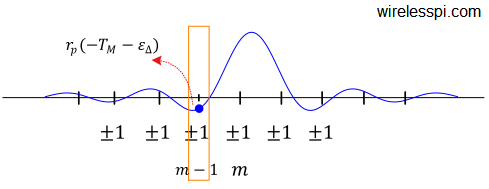
Proposed in 1976, Mueller and Muller algorithm is a timing synchronization technique that operates at symbol rate, as opposed to most other synchronization algorithms that require at least 2 samples/symbol such as early-late and Gardner timing error detectors. All of these are feedback techniques that operate within a PLL. Feedforward methods such as digital filter and square timing synchronization are also feasible due to powerful digital signal processing that avoids feedback problems such as hangups. The most confusing thing communication engineers and radio hobbyists find about Mueller and Muller algorithm algorithm is the cross product in its expression: matched filter

Continue reading
Square-root Nyquist filters for three different excess bandwidths

How to Design Nyquist and Square-Root Nyquist Pulse Shaping Filters

The radio spectrum is a very precious resource like real estate and must be utilized judiciously. Pulse shaping filters control the spectral leakage of the transmitted signal in a wireless channel due to the strict restrictions to comply with a spectral mask. This is even more important for the upcoming 5G wireless systems which are based on a variety of wireless transmission protocols (such as mobile networks, Internet of Things (IoT) and machine to machine communications) combined in one comprehensive standard. Even for wired channels, there is always a natural bandwidth of the medium (copper wire, coaxial cable, optical fiber)

Continue reading
A matched filter in continuous frequency domain along with the corresponding frequency matched filter for excess bandwidth 0.25

Band Edge Filters for Carrier and Timing Synchronization

Band edge filters for carrier frequency and symbol timing synchronization is a very interesting topic that elegantly relates the tool (DSP) to the application (SDR design). This article is a short summary of where they originate from and what role they play for synchronization purpose. A Carrier Frequency Offset (CFO) arises due to a mismatch between Tx and Rx local oscillators as well as a phenomenon known as Doppler effect. In some other articles on this website, you will also find information on the Phase Locked Loop (PLL) in the context of carrier phase and timing synchronization. There is another

Continue reading
Square-Root Raised Cosine (SR-RC) spectrum with different excess bandwidths

Modulation Bandwidths

From the article on pulse shaping, we can correctly determine the occupied bandwidth for each modulation scheme where the Square-Root Raised Cosine spectrum shows the bandwidth of a Square-Root Raised Cosine pulse shape as $0.5(1+\alpha)R_M$. Also, we have discussed earlier that the spectrum approximately remains the same, provided that there is enough randomness in bit stream and the resulting symbols are equally likely and independent from each other. Therefore, the bandwidth for a PAM modulated signal can be given as \begin{equation}\label{eqCommSystemBWPAM} BW_{\text{PAM}} = 0.5\left(1+\alpha\right)R_M \end{equation} QAM is basically a similar modulation scheme except that it is modulated on a carrier.

Continue reading
A block diagram for the implementation of a digital filter and square timing recovery for L=4 samples/symbol

Digital Filter and Square Timing Recovery

We have seen before how a symbol timing offset severely impacts the constellation of the received symbols. Therefore, symbol timing recovery is one of the most crucial jobs of a digital communications receiver. In the days of analog clock recovery, a timing error detector provided the instant to sample the Rx waveform at 1 sample/symbol at the maximum eye opening. However, discrete-time processing opened the doors for better timing recovery schemes as an ever increasing number of transistors within the same area consistently keeps bringing the digital processing cost down. Consequently, the use of analog circuits to control the timing

Continue reading