Complex sinusoids drawn to highlight the discrete frequency axis k on the left side

Discrete Frequency

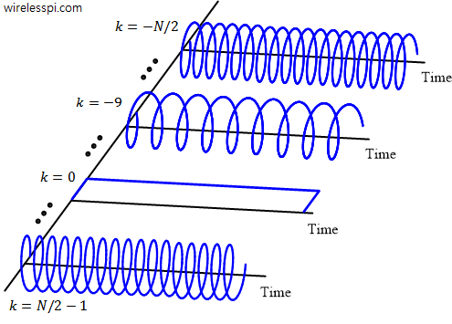
An Analog to Digital Converter (ADC) samples a continuous-time signal to produce discrete-time samples. For a digital signal processor, this signal just resides in memory as a sequence of numbers. Consequently, the knowledge of the sample rate $F_S$ is the key to signal manipulation in digital domain. As far as time is concerned, one can easily determine the period or frequency of such a signal stored in the memory. For example, the period $T$ in the sinusoid of Figure below is clearly $10$ samples and sample time $T_S=1/F_S$ can be employed to find its period in seconds. For a sample

Continue reading
Pacman circularly shifting to the right

Transforming a Signal

Transforming a discrete-time signal — whether in time or amplitude — is certainly possible, and often in interesting ways. In practice, scaling and time shifting are the two most important signal modifications encountered. Scaling changes the values of dependent variable on amplitude-axis while time shifting affects the values of independent variable on time-axis. Below we describe addition and multiplication of two signals as well as scaling and time shifting a signal in detail. Addition For addition of two discrete-time signals, say $x[n]$ and $y[n]$, add the two signals sample-by-sample: $z[n] = x[n] + y[n]$ for every $n$, e.g., \begin{align*} z[0]

Continue reading
Magnitude and phase of the DFT of a rectangular signal for L = 7, N= 16 and starting sample shifted by one

DFT Examples

For understanding what follows, we need to refer to the Discrete Fourier Transform (DFT) and the effect of time shift in frequency domain first. Here, we discuss a few examples of DFTs of some basic signals that will help not only understand the Fourier transform but will also be useful in comprehending concepts discussed further. A Rectangular Signal A rectangular sequence, both in time and frequency domains, is by far the most important signal encountered in digital signal processing. One of the reasons is that any signal with a finite duration, say $T$ seconds, in time domain (that all practical

Continue reading
A signal broken down into scaled and shifted impulses

Convolution

Understanding convolution is the biggest test DSP learners face. After knowing about what a system is, its types and its impulse response, one wonders if there is any method through which an output signal of a system can be determined for a given input signal. Convolution is the answer to that question, provided that the system is linear and time-invariant (LTI). We start with real signals and LTI systems with real impulse responses. The case of complex signals and systems will be discussed later. Convolution of Real Signals Assume that we have an arbitrary signal $s[n]$. Then, $s[n]$ can be

Continue reading

The Discrete Fourier Transform (DFT)

Learned in some other articles on this website, the following three important concepts take us to the core of the Discrete Fourier Transform (DFT) idea. Regardless of the signal shape, most signals of practical interest can be considered as a sum of complex sinusoids oscillating at different frequencies. A set of $N$ orthogonal complex sinusoids can be constructed within a span of $N$ time domain samples. Each `tick’ or bin on the discrete frequency axis denotes the discrete frequency $k/N$ of such a complex sinusoid. To understand how a set of sinusoids with $N$ discrete frequencies can sum up to

Continue reading