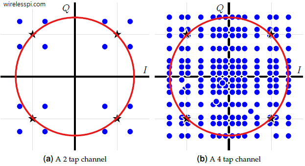
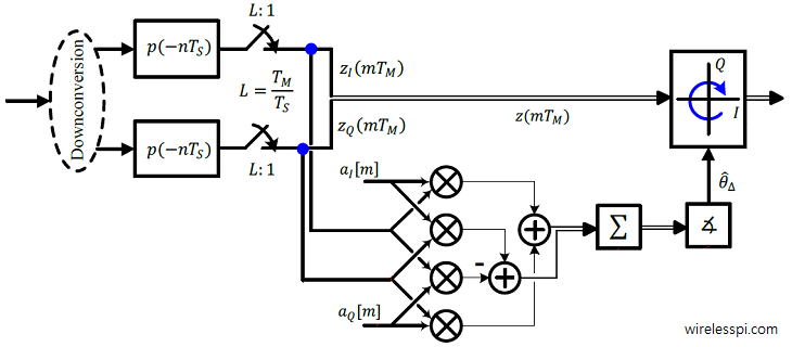
In this article, I will describe how to estimate the carrier phase from an incoming waveform in a feedforward manner. This algorithm utilizes a sequence of known pilot symbols embedded within the signal along with the unknown data symbols. Such a signal is sent over a link in the form of separate packets in burst mode wireless communications. In most such applications with short packets, the phase offset $\theta_\Delta$ remains constant throughout the duration of the packet and a single shot estimator is enough for its compensation. Here, the primary task of the designer is to develop this closed-form expression
Continue readingTag: Quadrature Amplitude Modulation (QAM)
What is Carrier Frequency Offset (CFO) and How It Distorts the Rx Symbols
In Physics, frequency in units of Hz is defined as the number of cycles per unit time. Angular frequency is the rate of change of phase of a sinusoidal waveform with units of radians/second. \begin{equation*} 2\pi f = \frac{\Delta \theta}{\Delta t} \end{equation*} where $\Delta\theta$ and $\Delta t$ are the changes in phase and time, respectively. A Carrier Frequency Offset (CFO) usually arises due to two reasons. The video below also explains this concept. [Frequency mismatch between the Tx and Rx oscillators] No two devices are the same and there is always some difference between the manufacturer’s nominal specification and the
Continue readingQuadrature Amplitude Modulation (QAM)
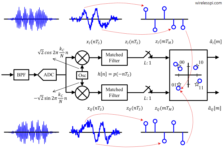
Quadrature Amplitude Modulation (QAM) is a spectrally efficient modulation scheme used in most of the high-speed wireless networks today. We discussed earlier that Pulse Amplitude Modulation (PAM) transmits information through amplitude scaling of the pulse $p(nT_S)$ according to the symbol value. To understand QAM, two routes need to be traversed. Route 1 We start the first route with differentiating between baseband and passband signals. A baseband signal has a spectral magnitude that is nonzero only for frequencies around origin ($F=0$) and negligible elsewhere. An example spectral plot for a PAM waveform is shown below for 500 2-PAM symbols shaped by
Continue readingModulation Bandwidths
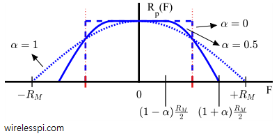
From the article on pulse shaping, we can correctly determine the occupied bandwidth for each modulation scheme where the Square-Root Raised Cosine spectrum shows the bandwidth of a Square-Root Raised Cosine pulse shape as $0.5(1+\alpha)R_M$. Also, we have discussed earlier that the spectrum approximately remains the same, provided that there is enough randomness in bit stream and the resulting symbols are equally likely and independent from each other. Therefore, the bandwidth for a PAM modulated signal can be given as \begin{equation}\label{eqCommSystemBWPAM} BW_{\text{PAM}} = 0.5\left(1+\alpha\right)R_M \end{equation} QAM is basically a similar modulation scheme except that it is modulated on a carrier.
Continue readingHow a Frequency Locked Loop (FLL) Works
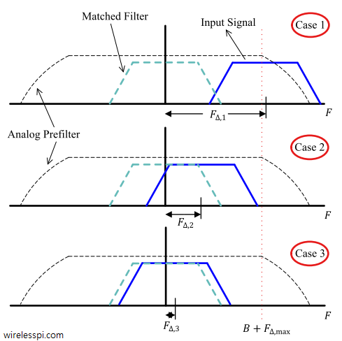
We saw before how a carrier frequency offset distorts the received signal. Later, we also described the classification of frequency synchronization techniques according to the availability of the symbol timing. Today, we will learn about the workings of a frequency locked loop. Background A Phase Locked Loop (PLL) is a device used to synchronize a periodic waveform with a reference periodic waveform. It is an automatic control system in which the phase of the output signal is locked to the phase of the input reference signal. In the article referred above, we also discussed that for a very small frequency
Continue reading