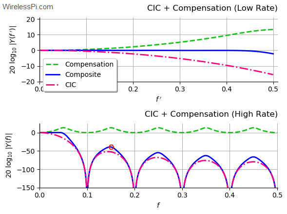
Spectrum of the cascade of CIC filters with a wideband compensation filter for rate change factor 10, unit differential delay and 4 stages

Cascaded Integrator Comb (CIC) Filters – A Staircase of DSP

In olden days, people used to have lots of kids. A famous Urdu satirist once wrote: "It has been observed that the last kid is usually the most mischievous of them all. Therefore, there should be no last kid in a family!" I remembered this line today because I have observed that starting a write-up is the most difficult task of them all. Therefore, there is no introductory paragraph in this article. Suffice it to say that this is the only topic I have found that takes you from a very small first step (just two additions) to really advanced

Continue reading
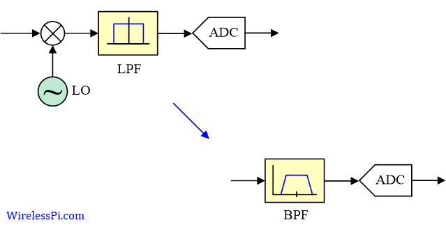
Bandpass sampling

On Analog-to-Digital Converter (ADC), 6 dB SNR Gain per Bit, Oversampling and Undersampling

We have discussed before the sampling on time axis for analog to digital (A/D) conversion. An Analog to Digital Converter (ADC) produces the samples $x[n]$ of a continuous-time signal $x(t)$ at its input. Ideally, these samples are the exact values of the signal $x(t)$ at time instants $nT_s$ where $T_s=1/f_s$ is the sampling period. In practice, however, there are imperfections both on the y-axis and the x-axis. On y-axis, an ADC has a finite resolution depending on the number of bits used for quantization. On x-axis, there are issues of clock jitter that distort the samples produced. In this article,

Continue reading
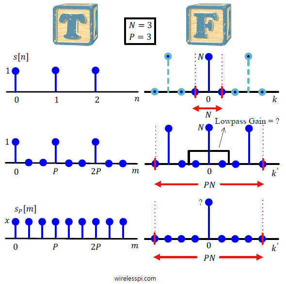
A rectangular signal and its upsampled version in time and frequency domains

Sample Rate Conversion

In the discussion on sampling, the process of sampling a continuous-time signal was discussed in detail and subsequently sampling theorem was derived. In many applications, resampling an already digitized signal is mandatory for an efficient system design. In wireless communications, sample rate conversion is utilized for upconversion and downconversion to a desired frequency, filtering stages in the digital frontend and sometimes for carrier and timing synchronization during signal acquisition. See the Cascade Integrator Comb (CIC) filters for how to accomplish this task with minimal resources. In discrete domain, sample rate can be reduced by discarding intermediate samples periodically called downsampling

Continue reading
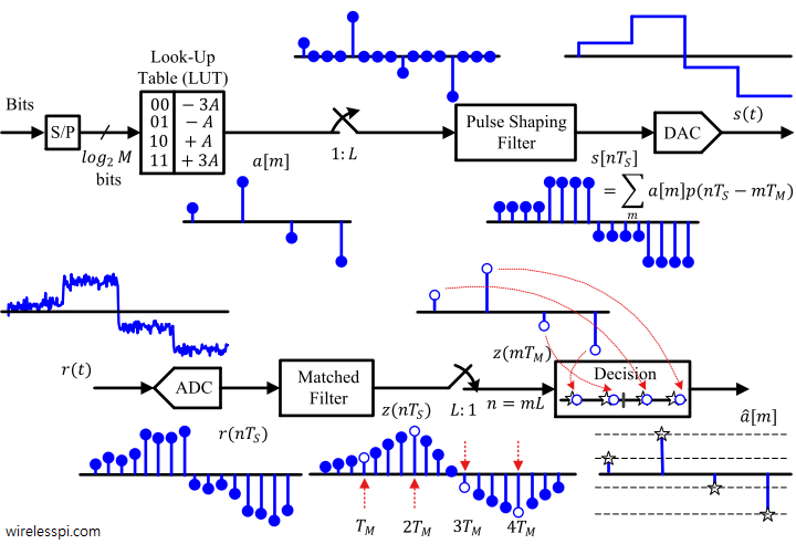
Block diagram of a pulse amplitude modulator and demodulator

Pulse Amplitude Modulation (PAM)

In the article on modulation – from numbers to signals, we said that the Pulse Amplitude Modulation (PAM) is an amplitude scaling of the pulse $p(nT_S)$ according to the symbol value. What happens when this process of scaling the pulse amplitude by symbols is repeated for every symbol during each interval $T_M$? Clearly, a series of bits $b$ (1010 in our initial example) can be transmitted by choosing a rectangular pulse and scaling it with appropriate symbols. \begin{equation*} \begin{aligned} m = 0 \quad b = 1 \quad a[0] = +A \\ m = 1 \quad b = 0 \quad a[1]

Continue reading