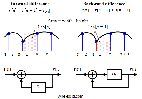
Band edge filters for carrier frequency and symbol timing synchronization is a very interesting topic that elegantly relates the tool (DSP) to the application (SDR design). This article is a short summary of where they originate from and what role they play for synchronization purpose. A Carrier Frequency Offset (CFO) arises due to a mismatch between Tx and Rx local oscillators as well as a phenomenon known as Doppler effect. In some other articles on this website, you will also find information on the Phase Locked Loop (PLL) in the context of carrier phase and timing synchronization. There is another
Continue readingCategory: DSP
Digital Signal Processing
Finite Impulse Response (FIR) Filters
We learned in the concept of frequency that most signals of practical interest can be considered as a sum of complex sinusoids oscillating at different frequencies. The amplitudes and phases of these sinusoids shape the frequency contents of that signal and are drawn through magnitude response and phase response, respectively. In DSP, a regular goal is to modify these frequency contents of an input signal to obtain a desired representation at the output. This operation is called filtering and it is the most fundamental function in the whole field of DSP. It is possible to design a system, or filter,
Continue readingDFT-Precoded OFDM
One of the drawbacks of an OFDM waveform is its high Peak to Average Power Ratio (PAPR). This high PAPR arises from the fact that a set of $N$ QAM symbols are taken into time domain through an inverse Fourier Transform (iFFT) operation that basically generates a combination of complex sinusoids scaled by those symbols. Due to the variations between the symbol values and the sinusoids with different frequencies, the output waveform can have a large variance in amplitudes. This reduces the power amplifier efficiency that results in faster battery drainage in a mobile terminal. The effect on base station
Continue readingThe Concept of Frequency
A wireless signal from one device to another travels through the use of electromagnetic waves propagated by an antenna. Electromagnetic waves have different frequencies and one can pick up a specific signal by tuning a radio Rx to a specific frequency. But what is a frequency anyway? Watch the video below for an interesting description of actual time domain samples and how to interpret their frequency domain representation. A Complex Sinusoid Consider a complex number $V$ in an $IQ$-plane. A complex number is defined as a pair of real numbers in $(x,y)$-plane similar to the vectors but with different arithmetic
Continue readingTools for Signal Diagnosis
In this article, we will devise some tools that help us diagnose problems with the communication system under study. I like to call them the stethoscopes for a communication system due to the crucial functionality they provide regarding the health of the communication system being analyzed. We discuss three such tools, namely an eye diagram, a transition diagram and a scatter plot below. Eye Diagram An eye diagram is an excellent summary of the signal behaviour in time domain, something analogous to a spectrum in frequency domain. Imagine the samples of the matched filter output taken at a much higher
Continue reading