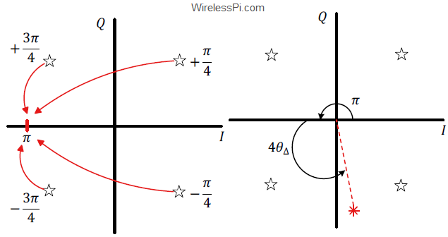
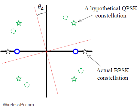
We have discussed before the effect of a phase offset on the received signal. We have also seen a logical approach to solve this problem as well as one of the earliest algorithms for phase synchronization known as a Costas loop. Here, the purpose is to explain how a Rx detects whether the Phase Locked Loop (PLL) has acquired the lock. A receiver is simply a blind machine which can implement a PLL but can never get to know how it is actually doing. A lock detector is a logic signal used in the Rx to indicate successful synchronization after
Continue readingTag: Quadrature Phase Shift Keying (QPSK)
Computing Error Rates
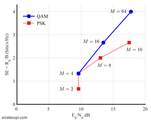
Having built a simple digital communication system, it is necessary to know how to measure its performance. As the names say, Symbol Error Rate (SER) and Bit Error Rate (BER) are the probabilities of receiving a symbol and bit in error, respectively. SER and BER can be approximated through simulating a complete digital communication system involving a large number of bits and comparing the ratio of symbols or bits received in error to the total number of bits. Hence, \begin{equation}\label{eqCommSystemSER} \text{SER} = \frac{\text{No. of symbols in error}}{\text{Total no. of transmitted symbols}} \end{equation} and \begin{equation}\label{eqCommSystemBER} \text{BER} = \frac{\text{No. of bits in
Continue readingHow a Frequency Locked Loop (FLL) Works
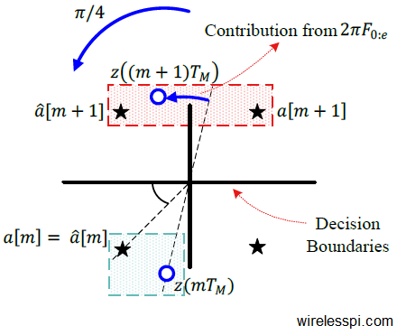
We saw before how a carrier frequency offset distorts the received signal. Later, we also described the classification of frequency synchronization techniques according to the availability of the symbol timing. Today, we will learn about the workings of a frequency locked loop. Background A Phase Locked Loop (PLL) is a device used to synchronize a periodic waveform with a reference periodic waveform. It is an automatic control system in which the phase of the output signal is locked to the phase of the input reference signal. In the article referred above, we also discussed that for a very small frequency
Continue reading