A bank of N filters each centered at discrete frequency k/N

Discrete Fourier Transform (DFT) as a Filter Bank

We have discussed before what a Discrete Fourier Transform (DFT) is and how to find the DFT of some commonly used signals. Here, we will see how a DFT acts as a (crude) bank of filters that can pass the signal contents around a desired frequency while blocking the rest. Let us start with the definition of the DFT. \begin{equation*} \begin{aligned} S_I[k]\: &= \sum \limits _{n=0} ^{N-1}\left[ s_I[n] \cos 2\pi\frac{k}{N}n + s_Q[n] \sin 2\pi\frac{k}{N}n\right] \\ S_Q[k] &= \sum \limits _{n=0} ^{N-1}\left[ s_Q[n] \cos 2\pi\frac{ k}{N}n – s_I[n] \sin 2\pi\frac{k}{N}n\right] \end{aligned} \end{equation*} for each $k$. In complex notation, this DFT is

Continue reading
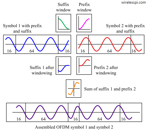
At the boundary of two OFDM symbols, pulse shaping smoothes the edges, resulting in the avoidance of spectral regrowth

Windowing an OFDM Signal in Time Domain

Orthogonal Frequency Division Multiplexing (OFDM) has been introduced in a previous article as a technique suitable for high data-rate transmissions over a wireless channel. The two main advantages I mentioned were as follows: Simple one-tap equalization, and Ability to slice the spectrum and utilize each slice in an independent manner. Due to these advantages, it was adopted as the preferred modulation in WiFi and 4G-LTE systems. The interesting part is that while many new waveforms were proposed to replace it in 5G NR, OFDM was still the modulation of choice for both downlink and uplink directions with some minor changes.

Continue reading
mmWave and THz bands

An Introduction to mmWave Band

Rising wireless traffic demands a continuous improvement in aggregate data rates delivered within a geographical area. One of the fundamental resources to achieve this goal is increasing the bandwidth. A wider bandwidth directly translates into higher throughput, just like increasing the number of lanes on a road directly impacts the traffic handled at peak times. This is the original reason for opening up the higher GHz and THz bands where vast amounts of empty spectrum is available. A bird’s eye view of the history of wireless transmission reveals that the wireless throughput increase during the past century has relied far

Continue reading
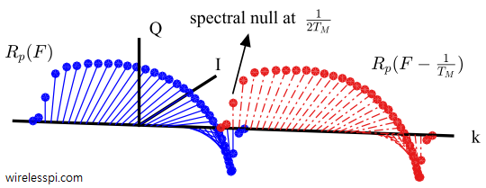
Spectrum of the Nyquist pulse and its symbol rate shifted version exhibit a spectral null at 0.5 symbol rate for a 0.5 timing offset

What is a Symbol Timing Offset and How It Distorts the Rx Signal

Timing synchronization is one of the most fascinating topics in the field of digital communications. On the bright side, numerous scientists have contributed towards its body of knowledge due to its crucial role in the successful implementation of communication and storage systems. On the not-so-bright side, this knowledge has grown to an extent that it has also become the least understood and puzzling topic in the grand scheme of things. My objective in this article is to simplify the problem in a clear and intelligible manner, and also refer to some of the most widely used solutions within the explanation.

Continue reading
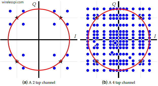
Scatter plot for a QPSK signal after filtering through a channel

An Introduction to Constant Modulus Algorithm (CMA)

In many kinds of equalizers such as maximum likelihood sequence estimation, the channel response is available at the Rx through any channel estimation procedure that requires a training sequence. For adaptive equalization such as Least Mean Square (LMS) equalizers or Decision Feedback Equalization (DFE), first the training sequence symbols and then symbol decisions are employed to tune the equalizer taps. There are many applications, however, where the Rx needs to acquire the equalizer coefficients without any help from the Tx in the form of known symbols. This is a non-data-aided scenario that is primarily required in mobile communication systems where

Continue reading