A quasi-static assumption implies that the channel stays the same for each block but varies from one block to the next

A Time-Varying Wireless Channel

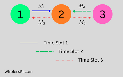
Today we will discuss three strategies that are usually adopted for handling a wireless channel that is varying with time and hence acting differently on different data symbols. For a channel impulse response $c(t)$, number of multipath $N_{MP}$, channel gains $\gamma_i(t)$ and delays $\tau_i(t)$ for the $i$-th path, respectively, we can write \begin{equation*} c_B(t) = \sum _{i=0}^{N_{MP} -1} \gamma_i(t) \cdot \delta(t-\tau_i(t)) \end{equation*} i.e., channel gains $\gamma_i(t)$ and channel delays $\tau_i(t)$ are varying with time albeit at different rates. With the movement in the channel, the taps in a frequency selective channel are changing according to the rotation rates of path

Continue reading

Interpreting Time Domain Derivative in Frequency Domain

Although this article explains the concepts in terms of mathematical constants e and j as well as integration, my book on SDR steers clear of the complex notation and integrals to describe the underlying concepts from the ground up to an advanced level. One of the properties of Fourier Transform is that the derivative of a signal in time domain gets translated to multiplication of the signal spectrum by $j2\pi f$ in frequency domain. This property is usually derived as follows. For a signal $s(t)$ with Fourier Transform $S(f)$ \begin{equation*} s(t) = \frac{1}{2\pi}\int \limits _{-\infty}^{+\infty} S(f) e^{j2\pi ft}df, \end{equation*} we

Continue reading
Bandpass sampling

On Analog-to-Digital Converter (ADC), 6 dB SNR Gain per Bit, Oversampling and Undersampling

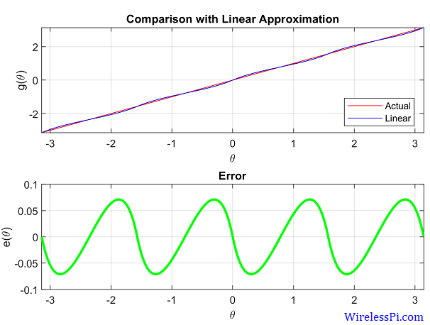
We have discussed before the sampling on time axis for analog to digital (A/D) conversion. An Analog to Digital Converter (ADC) produces the samples $x[n]$ of a continuous-time signal $x(t)$ at its input. Ideally, these samples are the exact values of the signal $x(t)$ at time instants $nT_s$ where $T_s=1/f_s$ is the sampling period. In practice, however, there are imperfections both on the y-axis and the x-axis. On y-axis, an ADC has a finite resolution depending on the number of bits used for quantization. On x-axis, there are issues of clock jitter that distort the samples produced. In this article,

Continue reading
Diversity implies two or more independent replicas of the same information

Multiple Antenna Techniques

When computing approaches the physical limits of clocking speeds, we turn towards multi-core architectures. When communication approaches the physical limits of transmission speeds, we turn towards multi-antenna systems. What exactly are the benefits that led to scientists and engineers choosing multiple antennas as the foundation of 4G and 5G PHY layers? While having spatial diversity was the original incentive for adding antennas at the base stations, it was discovered in mid 1990s that multiple antennas at Tx and/or Rx sides open up other possibilities not foreseen in single antenna systems. Let us now describe three main techniques in this context.

Continue reading
Average trajectory for squared eye diagrams for a binary PAM sequence of 400 symbols shaped with Raised Cosine pulse with excess bandwidths 0, 0.5 and 1

Lock Detectors for Symbol Timing Synchronization

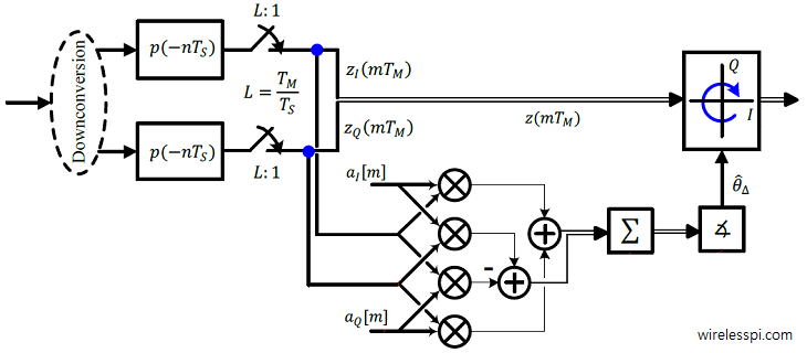
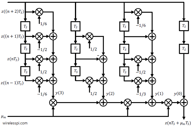
Similar to the carrier lock detectors, timing lock detectors can also be constructed based on some property of the modulated signal. These lock detectors operate in parallel to the timing locked loop and aid the Rx state machine in executing necessary tasks according to each scenario. The expressions for two such timing lock detectors are as follows. The output of a timing lock detector should be at its peak for the correct timing. Therefore, when the matched filter output, denoted by $z(mT_M)$ with $T_M$ being the symbol time, is at its peak, the second sample in a signal oversampled by

Continue reading