A wired channel such as an optical fiber or a coaxial cable carries the communication signal within a confined material. In contrast, a wireless channel has a broadcast nature in which the transmitted signal propagates in a 3D space in several directions. This gives rise to the multipath nature of this medium.
In a multiuser scenario, this problem takes an interesting turn. A signal transmitted by any node reaches several nodes due to this property. Except the one for which the signal is intended, each node treats this transmission as an interference which is overcome through careful receiver design or transmission scheduling. Physical Layer Network Coding (PNC) is a mechanism through which this problem can be transformed into a capacity boosting opportunity. Let us find out how.
Background
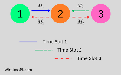
Consider a 3-node linear network shown in the figure below. Node 2 is a neighboring node to both 1 and 3, but the distance between nodes 1 and 3 is large enough to keep them out of each other’s transmission range. This is an opportunity for node 2 to act as a relay.

Such a three node network has been extensively studied for the purpose of cooperative transmission in which the relay node 2 can adapt a particular transmission strategy according to the Signal to Noise Ratio (SNR). We consider the following scenario for further investigation.
- Each node in the above network is equipped with an omni-direction antenna with equal gain in all directions.
- In cooperative transmission, common relaying strategies are Amplify-and-Forward (AF) and Decode-and-Forward (DF). In AF, the relay node simply amplifies and retransmits the signal onwards without looking under the hood, i.e., the message contents. On the other hand, a DF relay decodes the original message first and then re-modulates and retransmits the signal towards the destination.
- The nodes communicate in units of fixed-sized frames and one time slot implies the duration required for transmission of one frame.
- The communication framework is half-duplex and hence the transmission and reception at each node occur in different time slots.
We first describe the simple scheduling scheme with time orthogonality.
Simple Time Division Multiplexing
Interference among the nodes is avoided in conventional networks through orthogonality in a time division multiplexed system, as shown in the figure below.

Orthogonality in time, for instance, means that both node 1 and 3 do not communicate with node 2 in the same time slot. Otherwise, interference among the signals will prevent node 2 from decoding any of the messages correctly.
- In the first time slot, node 1 sends a frame $M_1$ containing bits $b_1$ to node 2 that is intended for node 3.
- In the second time slot, node 2 forwards this message to node 3.
- In the third time slot, node 3 replies with its own frame $M_3$ containing bits $b_3$ towards node 2.
- In the fourth time slot, node 2 relays this message back to node 1.
Therefore, a total of 4 time slots are required for the exchange of two messages or frames between nodes 1 and 3.
Let us explore how network coding makes this process more efficient by reducing the number of time slots.
Conventional Network Coding
As shown in the figure below, a typical network coding scheme works as follows.

- In the first time slot, node 1 sends a frame $M_1$ containing bits $b_1$ to node 2.
- In the second time slot, node 3 sends its frame $M_3$ with bits $b_3$ to node 2.
- After receiving both of these signals, node 2 encodes a frame $M_2$ of bits $b_2$ as follows.
\[
b_2 = b_1 \oplus b_3
\]where $\oplus$ denotes a bitwise exclusive OR (xor) operation over the entire frames $M_1$ and $M_3$. In the third time slot, node 2 broadcasts this constructed message $M_2$ to both nodes 1 and 3. Now when the node 1 can extract the the bits in $M_3$ using its own frame $M_1$ as follows.
\[
b_1 \oplus b_2 = b_1 \oplus (b_1 \oplus b_3) = b_3
\]Node 3 can extract the bits $b_1$ in a similar manner.
As a consequence of this strategy, a total of 3 time slots are required instead of 4 for this exchange. This improves the network throughput by $4/3=1.33$ or $33\%$ over the simple time-orthogonal scheme.
Now we can turn our attention towards physical layer network coding technique.
Physical Layer Network Coding (PNC)
Physical Layer Network Coding is based on the following idea.
Main Idea
In the 3rd time slot in conventional network coding, the relay node 2 broadcasts $b_1\oplus b_3$. Why does it have to wait for the 3rd time slot? Because nodes 1 and 3 take turns to send their frames to the relay during their assigned time slots.
If the relay then adds the two symbols (or bits) together using the internal Arithmetic Logic Unit (ALU) of its computer, then the same result can be achieved at its Rx antenna if the nodes 1 and 3 simultaneously broadcast their messages. Why? Because signals arriving at a Rx antenna are summed by nature. After all, the received signal is nothing but vibrations of electrons in proportion to the electromagnetic field observed at the antenna. And the electromagnetic field appearing at the antenna is sum of all the transmissions present in the air at that time.
Mapping
Let us explore the signal level view of the above setup.
- Both nodes 1 and 3 use Binary Phase Shift Keying (BPSK) modulation to encode their data bits.
- Carrier synchronization and symbol timing synchronization at the relay are perfect.
- Power control at transmitters is employed to maintain equal amplitude at the relay which is normalized to 1 in the coming discussion.
In such a situation, the signal arriving at the node 2 during one symbol time is given by
\[
\begin{aligned}
r_2(t) &= a_1 \cos (\omega t +\phi) + a_3 \cos (\omega t+\phi) \\\\
&= (a_1+a_3) \cos (\omega t +\phi) \\\\
&= c_2 \cos (\omega t +\phi)
\end{aligned}
\]
where $a_1$ and $a_3$ are BPSK symbols originating from node 1 and 3, respectively. They are mapped from bits $b_1$ and $b_3$, respectively, according to the familiar BPSK relation
\[
a_i = 2b_i-1
\]
This mapping generates a symbol $-1$ for bit 0 and $+1$ for bit 1. As a consequence, we have the following table for $c_2$ at the relay.
| Bit $b_1$ | Bit $b_3$ | Symbol $a_1$ | Symbol $a_3$ | At Relay $c_2=a_1+a_3$ |
|---|---|---|---|---|
| 1 | 1 | 1 | 1 | 2 |
| 0 | 1 | -1 | 1 | 0 |
| 1 | 0 | 1 | -1 | 0 |
| 0 | 0 | -1 | -1 | -2 |
The mapping at the relay (node 2) is now done according to the following table.
| At Relay $c_2=a_1+a_3$ | Bit $b_2$ | Symbol $a_2$ |
|---|---|---|
| 2 | 0 | -1 |
| 0 | 1 | 1 |
| 0 | 1 | 1 |
| -2 | 0 | -1 |
From the above two tables, notice that a mapping of $\{-2,2\}$ to 0 and 0 to 1 for bit $b_2$ imitate an xor operation similar to conventional network coding.
\[
b_2 = b_1 \oplus b_3
\]
The relay node then broadcasts the frame $M_2$ to both nodes 1 and 3. Upon successful demodulation of $b_2$, each of these nodes can compute the information bit of the other node. At node 1, for example, we have
\[
b_1 \oplus b_2 = b_1 \oplus (b_1 \oplus b_3) = b_3
\]
The reader can verify the correct bit $b_3$ from the above two tables for all four cases. Node 3 can detect $b_1$ in a similar manner.
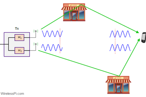
In light of the above, there is no need for two separate time slots for nodes 1 and 3. Instead, their simultaneous transmission xor’s their signals at node 2 antenna. A figure depicting Quadrature Amplitude Modulated (QAM) signals at both nodes 1 and 3 is drawn below.

It is clear that carrier and timing synchronization among the nodes is required to add the modulated carriers in phase.
Gain
Comparing with the previous figures on simple time division multiplexing and conventional network coding, we can see the number of time slots reducing from 4 to 2. This improves the network throughput by $4/2=2$ or $100\%$ over the simple time-orthogonal scheme and $3/2=1.5$ or $50\%$ over conventional network coding.
Conclusion
Physical Layer Network Coding (PNC) has the potential to greatly improve the throughput of multi-hop wireless networks. While conventional resource scheduling focuses on mitigating interference from simultaneous electromagnetic waves emitted by multiple nodes, PNC capitalizes on interference to perform network coding directly at the physical layer during signal modulation and demodulation.
References
[1] S. Zhang , S. Liew , P. Lam, Physical Layer Network Coding, MobiCom 2006.