A Phase Locked Loop (PLL) for digital symbol timing recovery

Phase Locked Loop (PLL) for Symbol Timing Recovery

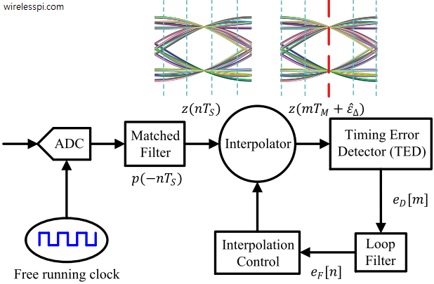
A Phase Locked Loop (PLL) is a device used to synchronize a periodic waveform with a reference periodic waveform. It is an automatic control system in which the phase of the output signal is locked to the phase of the input reference signal. In the context of carrier phase synchronization, we talk about tracking the phase of an input reference sinusoid. For carrier frequency synchronization, a Frequency Locked Loop (FLL) is implemented. For the purpose of timing synchronization, the target is to adjust the timing phase of a receiver clock to that of the transmitter clock such that one sample/symbol

Continue reading
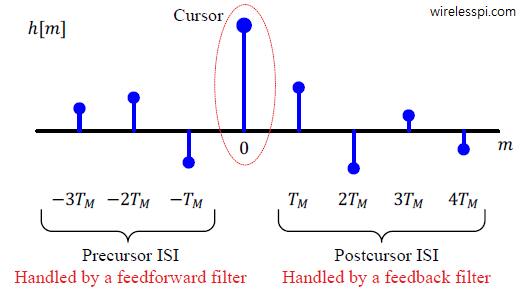
A channel with 8 taps demonstrating the main cursor, precursor ISI and postcursor ISI

How Decision Feedback Equalizers (DFE) Work

We started the classification of equalization algorithms by introducing the need for equalization in wireless communication systems. We said that the wireless channel is a source of severe distortion in the received (Rx) signal and our main task is to remove the resulting Inter-Symbol Interference (ISI) from the Rx samples. Equalization refers to any signal processing technique in general and filtering in particular that is designed to eliminate or reduce this ISI before symbol detection. In essence, the output of an equalizer should be a Nyquist pulse for a single symbol case. A conceptual block diagram of the equalization process

Continue reading
Block diagram of a 4 symbol communication system

Packing More Bits in One Symbol

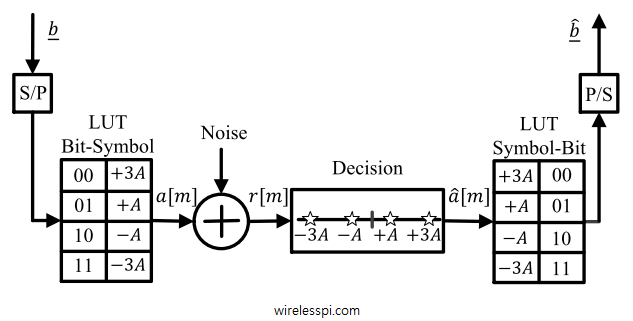
Note that digital electronics are constrained to work on only two levels by electronic switches which in the simplest case are either on or off. For many reasons, practical digital communication systems require quite complicated signal processing workload both at the Tx and Rx ends that can be performed only by a device more intelligent than an electronic switch, such as an Application Specific Integrated Circuit (ASIC), Field Programmable Gate Array (FPGA), Digital Signal Processor (DSP) or a General Purpose Processor (GPP). If this intelligent device can differentiate between two signal levels like a switch, it can certainly differentiate between

Continue reading
Frequency domain beamforming implements a procedure for broadband signals that resembles the conventional narrowband beamformers

Beamforming for Broadband Signals

Recall that classical or physical beamforming is based on calculating the differences in wave arrival times of a signal between antenna array elements and compensating for these delays through signal processing techniques that steer the beams in any desired direction. There are two main candidates for this purpose: Phase shifting and True Time Delays (TTD). We saw in that article on beamforming that phase shifts implemented through a set of complex multipliers are incapable of beamforming over the entire bandwidth of a signal. Why? The intuitive reason is clear from a signal level view. In the narrowband scenario, the same

Continue reading
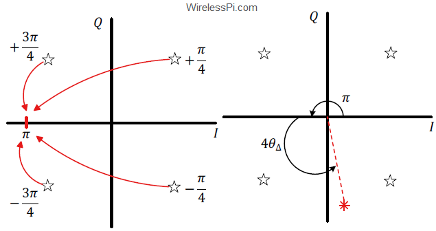
S-curve for decision-directed maximum likelihood phase error detector

What are Cycle Slips and Hangup in Phase Locked Loops?

In a previous article, we have covered in detail the inner workings of a Phase Locked Loop (PLL) in a Software Defined Radio (SDR). There are two phenomena that have the potential to occasionally disrupt the performance of a PLL operating in steady state: cycle slips and hangup. Both the carrier and timing locked loops suffer from these issues. The underlying mathematics is quite intricate and hence I give a simple overview of these concepts. A reader interested in further exploration is referred to [1]. Cycle Slips To understand the cycle slip, assume that the loop is in tracking mode,

Continue reading