We started the classification of equalization algorithms by introducing the need for equalization in wireless communication systems. We said that the wireless channel is a source of severe distortion in the received (Rx) signal and our main task is to remove the resulting Inter-Symbol Interference (ISI) from the Rx samples. Equalization refers to any signal processing technique in general and filtering in particular that is designed to eliminate or reduce this ISI before symbol detection. In essence, the output of an equalizer should be a Nyquist pulse for a single symbol case. A conceptual block diagram of the equalization process is shown in the figure below where the composite channel includes the effects of Tx/Rx filters and the multipath.

Background
Simple equalization techniques include linear algorithms such as Zero-Forcing and Minimum Mean Square Estimation (MMSE) equalizers. The most attractive feature of the linear equalizers is their simplicity: each output sample is a simple linear combination (determined by the equalizer taps) of the input samples. The cost of this simple implementation is their performance. While the minimum mean square error equalizer does not enhance the noise as much as the Zero-Forcing equalizer, its performance is still not acceptable in most practical scenarios.
Is it possible to design an equalizer that carries both features of simplicity and accuracy? While the answer is usually no in most situations, it is possible here to a certain extent through a Decision Feedback Equalizer (DFE).
Fundamental Idea
To understand the concept of decision feedback, we first introduce the notation for the relevant parameters.
- The $m$-th data symbol is denoted by $a[m]$ that represents an amplitude modulated system.
- The corresponding matched filter output is written as $z[m]$ that is input to the equalizer.
- The equalizer coefficients are given by $q[m]$.
- The equalizer output is the signal $y[m]$.
- The wireless channel impulse response is $h[m]$.
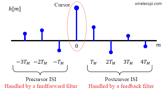
In the channel impulse response $h[m]$, remember that there is usually a main tap with the largest energy that represents the main symbol location. Let us call this tap the main cursor. The remaining channel taps contribute towards the Inter-Symbol Interference (ISI). This ISI manifests itself at two locations:
- before the cursor known as precursor ISI, and
- after the cursor known as postcursor ISI.
Since these terms can be a little confusing, let us build this concept from the fundamentals. Recall from the previous sections that for a symbol-spaced equalizer, the matched filter output $z[m]$ is generated by the convolution of the data symbols $a[m]$ with the composite channel impulse response $h[m]$.
\begin{equation*}
z[m] = a[m] * h[m] = \sum _{l=0}^{N} a[l]\cdot h[m-l]
\end{equation*}
where $N$ is the channel length in number of taps. Assume that the first four data symbols $a[m]$ are
\begin{equation*}
a[m] = \Big[+1 ~~-1 ~~-1~~+1 \Big]
\end{equation*}
and the channel consists of the following $4$ taps.
\begin{equation*}
h[m] = \Big[-0.5 ~~0.9 ~~-0.3 ~~0.2 \Big]
\end{equation*}
Also suppose that the Rx has complete knowledge of the channel through a channel estimation procedure. The two signals $a[m]$ and $h[m]$ are shown at the top of the figure below. Next, we invoke the intuitive explanation of convolution and draw the convolution steps in in the figure below from the viewpoint of symbol $a[2]$. I highly recommend you to read that intuitive view on convolution before continuing what follows, even if you already know about convolution.

- Symbol $a[0]$: The symbol $a[0]=1$ kicks out the first copy of the impulse response $h[m]$. The type of the channel implies that the cursor lies at the second tap at position $m=1$.
- Symbol $a[1]$: Now the symbol $a[1]=-1$ induces the second copy of $h[m]$ whose cursor lies at $m=2$.
- Symbol $a[2]$: This is the focus of our current discussion. The third symbol $a[2]=-1$ produces the third copy of $h[m]$ that starts at $m=2$. However, the cursor lies at time $m=3$. Observe the dashed red rectangle drawn at time $m=3$ encompassing the whole figure that contains the ISI injected by each symbol at this time. It is evident that symbols $a[0]$ and $a[1]$ cause the postcursor ISI through $4^{th}$ and $3^{rd}$ channel taps, respectively. Furthermore, symbol $a[3]$, a future symbol, induces the precursor ISI through the first channel tap.
But doesn’t the Rx already know the two symbols $a[0]$ and $a[1]$ as well as the complete channel information through which it can cancel their contributions? Yes, it does and that is the whole point of canceling the postcursor ISI as explained next.
If we open the convolution equation between the data symbols $a[m]$ and channel $h[m]$ at time $m=3$ (because the cursor for symbol $a[2]$ lies at time $m=3$), we get an interesting expression.
\begin{align*}
z[3] &= \sum _{l=0}^{N} a[l]\cdot h[3-l] \\
&= \underbrace{a[0]\cdot h[3] + a[1]\cdot h[2]}_{\text{Postcursor ISI}} + \underbrace{a[2]\cdot h[1]}_{\text{Cursor}} + \underbrace{a[3]\cdot h[0]}_{\text{Precursor ISI}}
\end{align*}
Compare these terms with the figure above where each subfigure in the red dashed rectangle corresponds to a term above. We can rewrite the above expression as
\begin{equation*}
z[3] – \left\{\underbrace{a[0]\cdot h[3] + a[1]\cdot h[2]}_{\text{Postcursor ISI}}\right\} = \underbrace{a[2]\cdot h[1]}_{\text{Cursor}} + \underbrace{a[3]\cdot h[0]}_{\text{Precursor ISI}}
\end{equation*}
After the training sequence ends and the data transmission starts, the decisions $\hat a[m]$ taken at each symbol instant $m$ can be employed to cancel the postcursor ISI. This is the idea of the decision feedback equalization. For example, standing at instant $m=2$,
\begin{equation}\label{eqEqualizationDecisionsFedBack}
z[3] – \left\{\underbrace{\hat a[0]\cdot h[3] + \hat a[1]\cdot h[2]}_{\text{Decision feedback}}\right\} = a[2]\cdot h[1] + a[3]\cdot h[0]
\end{equation}
A Summary
To summarize what we have learned so far, understand that each symbol generates both precursor ISI and postcursor ISI. Not much can be done regarding the symbols responsible for precursor ISI because it requires looking into the future symbols. This is only possible in an often undesirable delayed output scenario. On the other hand, once a symbol is detected, its effect from the future symbols, i.e., postcursor ISI, can be removed through a proper equalizer design. Let us find out how this is accomplished through a decision feedback equalizer.
Keep in mind that a decision feedback equalizer can be implemented with fixed or preset taps at the start of the transmission that remain so until the end, or its taps can be adapted according to the channel conditions through an adaptive algorithm like LMS.
Design of a Preset Decision Feedback Equalizer
The most straightforward idea to implement a decision feedback equalizer is to imitate what we did in decision-directed synchronization. We can scale the previously detected symbol $\hat a[m]$ through the corresponding channel tap $h[m]$ and subtract them from the matched filter output $z[m]$ that enters the threshold detector. This is the option presented by the left side of Eq (\ref{eqEqualizationDecisionsFedBack}).
Decision-Directed Equalization
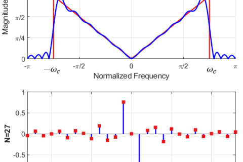
To illustrate the problem with this approach, consider the figure below that shows a channel with 8 taps. Only the postcursor ISI can be removed by the above mentioned strategy. There is a significant precursor ISI — a total of 3 taps to be exact — in the demonstrated channel that is going to cause decision errors. These decision errors will inject even more ISI in the system due to the wrong decisions fed back. Clearly, a 'decision-directed equalizer' is not a good solution for most channels. Let us discuss an alternative approach.

The Two Filters
A regular equalizer consists of $2L_q+1$ taps which act on the incoming signal $z[m]$ (the matched filter output) all at once to produce the output $y[m]$.
\begin{equation}\label{eqEqualizationEqOut}
y[m] = \sum _{l=-L_q}^{L_q} q[l]\cdot z[m-l]
\end{equation}
The strategy adopted by a Decision Feedback Equalizer (DFE) is to split the equalizer into two separate portions:
- a feedback filter that removes the postcursor ISI with the help of symbol decisions, and
- a feedforward filter that minimizes the ISI like a regular equalizer. It can be designed to handle either just the precursor portion of the ISI or all of it.
The structure of a decision feedback equalizer with two constituent filters is shown in the figure below.

Out of the total number of taps, $L_{\text{q,FF}}+1$ taps are assigned to the feedforward filter that are considered $T_M$-spaced in the current discussion. The remaining $L_{\text{q,FB}}$ taps are then assigned to the feedback filter.
\begin{equation*}
2L_q+1 = L_{\text{q,FF}} + 1 + L_{\text{q,FB}}
\end{equation*}
The exact division of the taps between these filters depends on the channel response. For example, a channel with a 'long tail' or a large postcursor ISI and less precursor ISI can have $L_{\text{q,FB}}$ greater than $L_{\text{q,FF}}+1$. Next, we find out how to implement such a technique.
With the matched filter output $z[m]$ as the equalizer input, we have the output $y[m]$ after splitting the equalizer in Eq (\ref{eqEqualizationEqOut}).
\begin{equation}\label{eqEqualizationDFE}
y[m] = \underbrace{\sum_{l=-L_{\text{q,FF}}}^{0} q_{\text{FF}}[l]\cdot z[m-l]}_{\text{Feedforward filter}} + \underbrace{\sum_{l=1}^{L_{\text{q,FB}}} q_{\text{FB}}[l]\cdot \hat a[m-l]}_{\text{Feedback filter}}
\end{equation}
where $q_{\text{FF}}[m]$ and $q_{\text{FB}}[m]$ are the taps for feedforward and feedback filter, respectively. The next question is how to choose these taps.
Feedforward Filter
As far as the feedforward filter $q_{\text{FF}}[m]$ is concerned, any criteria for handling the ISI can be chosen, e.g., zero forcing or minimum mean square error. In other words, the feedforward filter is a simple linear equalizer like Zero-Forcing. However, it does not need to approximate the inverse of the channel characteristics and its coefficients can be designed accordingly. For example, for a channel with a large precursor and small postcursor ISI, all the feedforward filter taps can be devoted to removing the precursor ISI (as long as the symbol decisions are correct, the postcursor ISI is removed by the feedback filter). Otherwise, the feedforward filter can be designed to reduce ISI from all the taps whether precursor or postcursor, just like a single equalizer would do.
Feedback Filter
On the other hand, it seems from Eq (\ref{eqEqualizationDecisionsFedBack}) that the coefficients $q_{\text{FB}}[m]$ of the feedback filter should simply be the channel taps $h[m]$ because the input to the feedback section is the data symbol decisions $\hat a[m]$, see the block diagram above. However, while deriving that equation, we did not have any feedforward filter to remove the precursor ISI and hence its input was directly the data symbols $a[m]$ convolved with the channel response $h[m]$. In this case, however, the input to the decision device (without a feedback equalizer) is expressed as
\begin{equation*}
y[m] = a[m] * h[m] * q_{\text{FF}}[m]
\end{equation*}
The term $h[m] * q_{\text{FF}}[m]$ is the modified channel that appears as the distortion to the feedback equalizer. In the light of Eq (\ref{eqEqualizationDecisionsFedBack}) with the modified channel whose effect needs to be cancelled out, the taps of the feedback filter can be written as the convolution of the channel response $h[m]$ with the feedforward filter taps $q_{\text{FF}}[m]$.
\begin{equation*}
q_{\text{FB}}[m] = h[m] * q_{\text{FF}}[m]
\end{equation*}
The final expression for the feedback taps is
\begin{aligned}
q_{\text{FB}}[m] = \sum _{l=-L_{\text{q,FF}}}^{0} &q_{\text{FF}}[l]\cdot h[m-l] \\
&\text{for each }m = 1,2,\cdots,L_{\text{q,FB}}
\end{aligned}
\end{equation}
Error Propagation
Removing the impact of $L_{\text{q,FB}}$ past symbols from the current symbol results in complete elimination of postcursor ISI as long as the fed back decisions are correct. Once that happens, the performance of a DFE is vastly superior to that of any linear equalizer.
- However, if the decisions are not correct, the errors are fed back generating more errors in a phenomenon known as error propagation.
- As a consequence, a DFE is a suitable design for a system operating at high SNR.
- But even at high SNR, a DFE cannot compensate for the timing offset sensitivity of a symbol-spaced equalizer.
- Finally, remember that a DFE is non-linear due to the inclusion of the detected symbols $\hat a[m]$ in the feedback filter.
Design of an Adaptive Decision Feedback Equalizer
As we saw in the case of LMS equalizer, the taps of both feedforward and feedback filters can also be adjusted in an iterative manner instead of fixing them to some determined values. Following the steps that lead to the final equation there, we have the following coefficients for the feedforward filter.
\begin{equation}\label{eqEqualizationDFELMSFF}
\begin{aligned}
q_l[m+1] = q_l[m] + 2 \mu &\cdot e[m]\cdot z[m-l]\\
&\text{for each }l = -L_{\text{q,FF}},\cdots,0
\end{aligned}
\end{equation}
where the subscript $l$ now denotes the $l^{th}$ tap, as opposed to the symbol time $m$. On the other hand, the coefficients of the feedback filter can be adjusted as
\begin{equation}
\begin{aligned}
q_l[m+1] = q_l[m] + 2 \mu &\cdot e[m]\cdot \hat a[m-l]\\
&\text{for each }l = 1,2,\cdots,L_{\text{q,FB}}
\end{aligned}
\end{equation}
Observe the appearance of the symbol decision $\hat a[m]$ instead of the matched filter output $z[m]$ in the above expression because the input to the feedback equalizer is the symbol decisions $\hat a[m]$. Rest of the details of the LMS algorithm for the DFE are the same as discussed before.
The application of decision feedback equalization is not restricted to individual symbols basis only. In recent times, the advent of powerful iterative error correcting codes which operate in units of large blocks have motivated decision feedback equalization in a block-wise fashion.
Hi,
Is there a matched filter in DFE structure? Can you explain more? Please email me.
Thanks
Yes, the filter is matched to the pulse shape (e.g., root raised cosine) and then the DFE equalizes the channel distortion.
Thanks. So please correct me if I am mistaken: (lets consider a simulation in Matlab that we want to transmit bunch of bits through channel using lets say BPSK).
First utilize a raised cosine filter (not root raised cosine) in transmitter for the sake of pulse shaping then it pass through channel with some Unknown coefficient but for simplicity we consider it is flat.
After that the transmitted symbols adds with noise(AWGN).
Finally in receiver we have a receive filter exactly like transmit filter and then we have DFE.
Is it correct?
Thanks again
It is partially correct.
Hello again.
I am working on this concept for a while. I have read section 17.4 of “Adaptive Filters: Theory and Applications” a book by Behrouz Farhang-Boroujeny. Fortunately, it has Matlab code which comparing Symbol-Spaced, Fractionally spaced and DF equalizers.
Through Matlab code it utilized up-sampling in the code which confused me. In the code optimum wights had been calculated but it lacks a simple example to show how it work. So, I am struggling to pass symbols through each block and see what it comes at the output. It seems straightforward to convolve input with each block (channel, optimum ff and fb wights and …) and test the code but I’ve been failure. It takes days of thinking and testing the code but no satisfying result.
All in all, I am asking to lend me a hand.
Thanks