Note that digital electronics are constrained to work on only two levels by electronic switches which in the simplest case are either on or off. For many reasons, practical digital communication systems require quite complicated signal processing workload both at the Tx and Rx ends that can be performed only by a device more intelligent than an electronic switch, such as an Application Specific Integrated Circuit (ASIC), Field Programmable Gate Array (FPGA), Digital Signal Processor (DSP) or a General Purpose Processor (GPP).
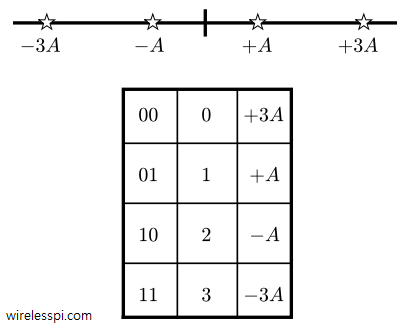
If this intelligent device can differentiate between two signal levels like a switch, it can certainly differentiate between more than two signal levels as well. Being able to do so can result in sending more data during the same amount of time. For example, Figure below shows four different symbols, $-3A$, $-A$, $+A$, and $+3A$. To develop a fair assignment of bits to symbols, consider a shift from binary number system to decimal number system. Clearly $0$, $1$, $2$ and $3$ can represent those four symbols with the help of the mapping shown in Figure below. Essentially, two bits can be collected during every unit of time (the symbol time $T_M$), converted into their decimal equivalent and a symbol, $-3A$, $-A$, $+A$, and $+3A$, can be chosen accordingly.
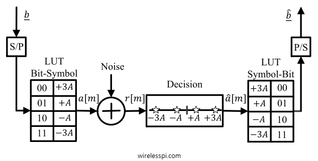
Similar to a simplest binary communication system, a digital communication system based on 4 symbols can be accordingly constructed as shown in Figure below. A serial-to-parallel (S/P) converter at the Tx collects multiple bits at a time. These bits, converted into their decimal representation, form an address to a unique symbol in a bit-symbol mapper called a Look-Up Table (LUT). After the addition of noise in the channel, the Rx performs its decisions according to the minimum distance rule, maps the resulting symbols back into bits and uses a parallel-to-serial (P/S) converter to generate back the target bit stream. Finding bit sequence from the estimate of symbol sequence is a matter of one-to-one mapping. Once the symbol decisions are formed, the resultant bits can automatically be known through an LUT.

Extending the above procedure, a certain number of bits can be combined and represented by one symbol to transmit information during every $T_M$ seconds. Combining two bits generates $2^2=4$ symbols. Extending the same reasoning, $2^b = M$ symbols are required to transmit $b$ bits of information. Hence, an $M$-symbol scheme transmits $\log_2 M$ bits of information every $T_M$ seconds. As an example, we need $8$ different symbols to send $3$ such bits.
In summary, a digital communication system sends a discrete set of numbers and tries to map the received values to (hopefully) the same discrete set of numbers. At this stage, the question arises: can these numbers – which are just symbols in the form of levels – be sent over real channels? The answer is no, and instead these numbers are converted to signals for transmission.