Frequency Modulation (FM) is one of the oldest communication techniques for high fidelity transmission. Its digital counterpart, Frequency Shift Keying (FSK), also plays a crucial role in applications requiring low receiver complexity. In an FSK scheme, digital information is transmitted by changing the frequency of a carrier signal. It can also be mixed with Chirp Spread Spectrum (CSS) for low-power long-range communication as used in LoRa PHY.
Binary FSK
Binary FSK (BFSK) is the simplest form of FSK where the two bits 0 and 1 correspond to two distinct carrier frequencies $F_0$ and $F_1$ to be sent over the air. The bits can be translated into symbols through the relations
\begin{equation*}
\begin{aligned}
0 \quad & \rightarrow \quad -1 \\
1 \quad & \rightarrow \quad +1
\end{aligned}
\end{equation*}
This enables us to write the two frequencies $F_i$ with $i ~ \epsilon ~ \{0,1\}$ as
\begin{equation*}
F_i = F_c + (-1)^{i+1} \cdot \Delta_F = F_c \pm \Delta_F
\end{equation*}
where $F_c$ is the nominal carrier frequency and $\Delta_F$ is the peak frequency deviation from this carrier frequency. The signal waveform can now be written as
\begin{equation}\label{eqFSKwaveform}
s(t) = A \cos \left(2\pi F_i t +\phi \right)= A \cos\Big[2\pi \big(F_c \pm \Delta_F\big) t + \phi\Big]
\end{equation}
where $0\le t \le T_b$ and $\phi$ is an arbitrary phase. Figure below displays a BFSK waveform for a random stream of data at a rate of $R_b = 1/T_b$. Note that we are not distinguishing between a bit period and a symbol period because both are the same for a binary modulation technique.

One of the most interesting modulation schemes in digital communication, namely Minimum Shift Keying (MSK), is a version of FSK. Let us turn towards the mostly used block for FSK demodulation in GNU Radio.
Quadrature Demod Block
As far as an FSK receiver is concerned, a commonly used method in GNU Radio implementations is the Quadrature Demod block. A block diagram of such a detector is reproduced below from GNU Radio wiki where the block Quadrature Demod is encircled in red. Here, a larger flowgraph can be viewed by clicking on the image below.
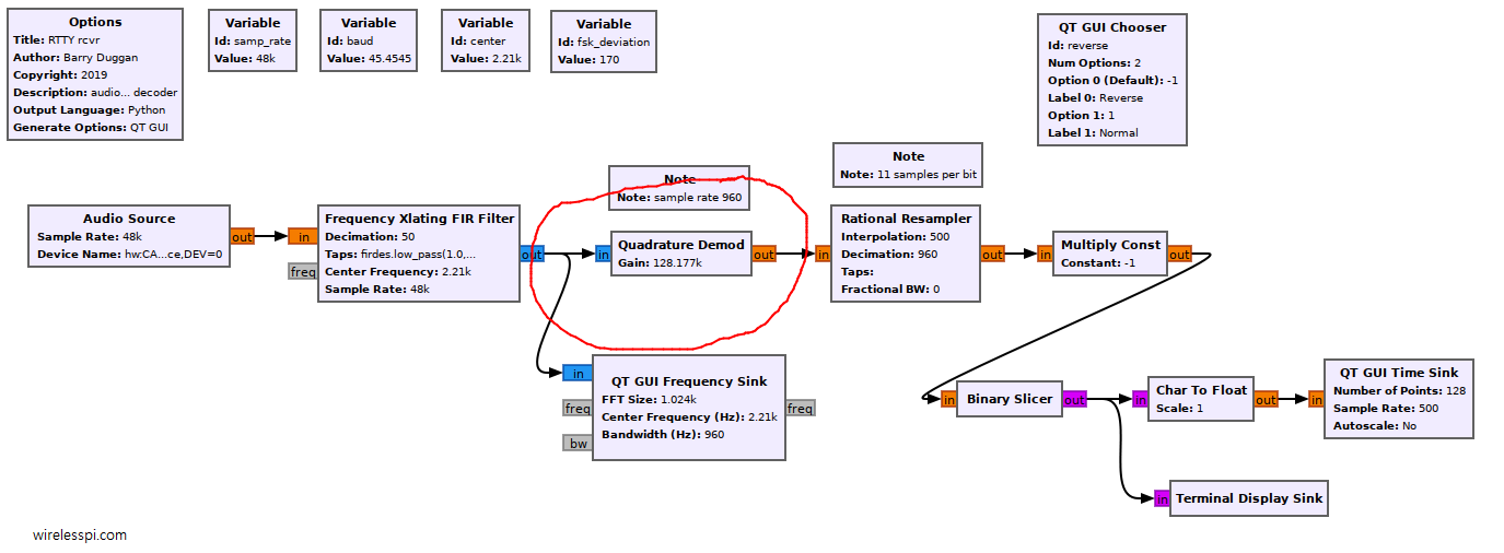
Such a structure can be used to demodulate several frequency modulation schemes such as FM, FSK and GMSK. The input to the block is the complex baseband waveform. Within the block, a product of the one-sample delayed input and the conjugate original signal is computed, the output of which is a complex number.
\begin{equation*}
z(nT_S) = s(nT_S)\cdot s^*\left[(n-1)T_S\right]
\end{equation*}
The argument of this complex number is the signal frequency relative to the sample rate multiplied with the gain, as we will see later.
Demodulating an FSK Signal
To see the role of a Quadrature Demod block in demodulating an FSK signal, let us consider a complex version of the FSK modulated signal described in Eq (\ref{eqFSKwaveform}) which just showed the real part.
\begin{equation*}
s(t) = A e^{j \left(2\pi F_i t + \phi\right)}
\end{equation*}
This signal is sampled at a rate of $F_S=1/T_S$ where $T_S$ is the sample period.
\begin{equation*}
s(nT_S) = A e^{ j \left(2\pi F_i nT_S + \phi\right)} = A e^{j \left(2\pi \frac {F_i}{F_S} n + \phi\right)}
\end{equation*}
Generating the Waveform
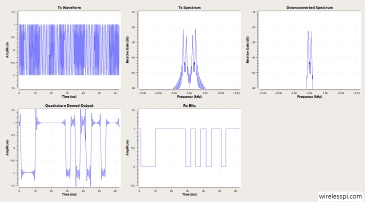
In a very simple GNU Radio Companion flowgraph below, an FSK waveform is generated with center frequency 1.5 kHz and a frequency deviation of 500 Hz. This results in two carrier waves, one at 1 kHz representing a 0 and the other at 2 kHz representing a 1. This is implemented in the following manner (click on the image to enlarge it).
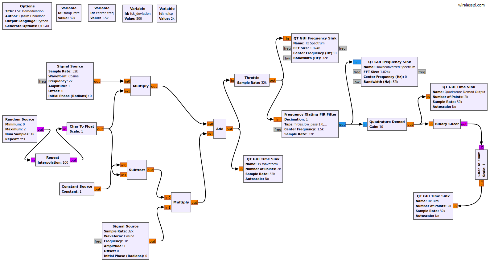
- Multiply the bits, e.g., 0,1,1,0,0,1,…, with the higher frequency wave at 2 kHz that produces a 2 kHz wave for 1 bits and a blank space of zeros for 0 bits.
- Multiply one minus the bits, e.g., 1- (0,1,1,0,0,1,…), with the lower frequency wave at 1 kHz that produces a 1 kHz wave for 0 bits and a blank space of zeros for 1 bits.
- Add the two waves together thus generating a BFSK waveform.
Frequency Xlating FIR Filter
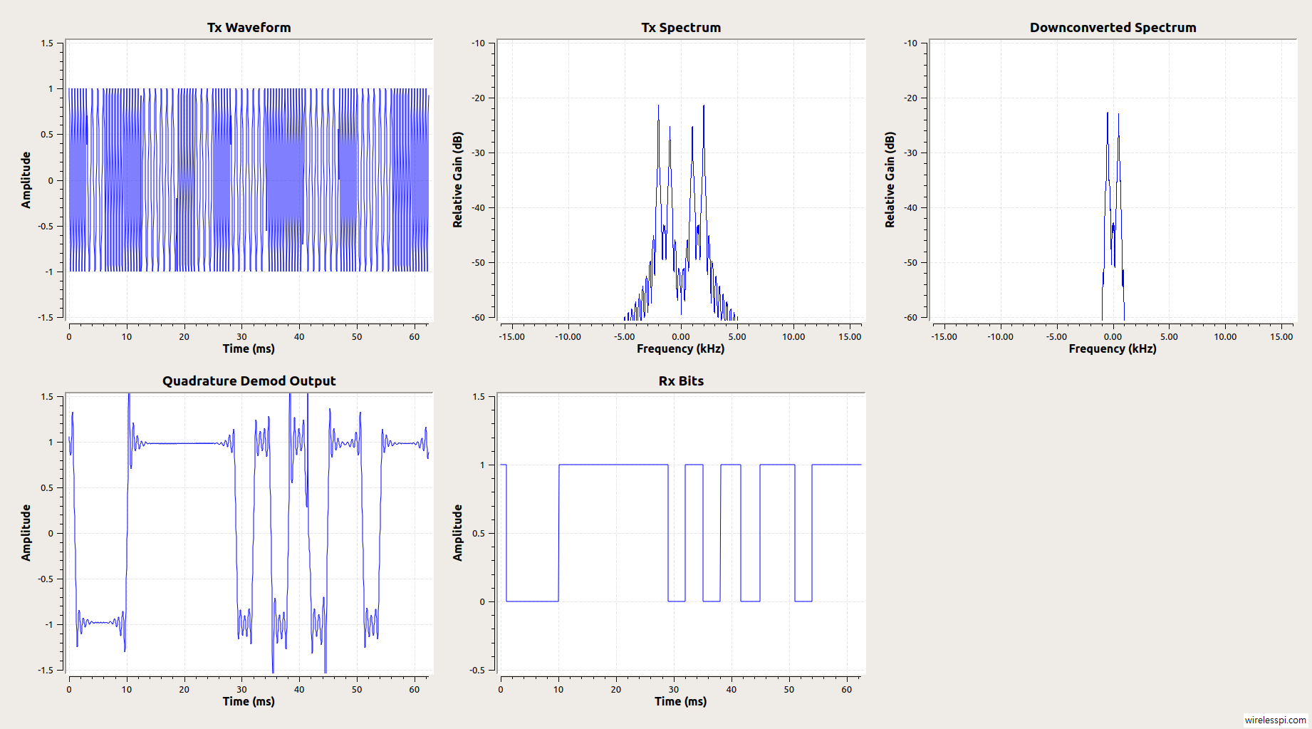
At the Rx side, a frequency translating FIR filter with a center frequency of 1.5 kHz is employed. According to its documentation, this block performs a frequency translation on the signal, as well as downsamples the signal by running a decimating FIR filter on it. This operation places the modulated signal at baseband and hence the two possible frequencies are now located at $\pm 500$ Hz. This is shown by two impulses at $\pm 500$ Hz below that is the output of the flowgraph described above (click on the image to enlarge it).
The command firdes.low_pass(1.0,samp_rate,900,300) uses a lowpass filter with unity gain, a sample rate of 32 kHz, a cutoff frequency of 900 Hz and a transition bandwidth of 300 Hz. According to GNU Radio documentation, the cutoff frequency is meant to be at the center of transition band in firdes.low_pass function. This implies that the edge of passband lies at 900-300/2=750 Hz, well beyond the impulse location of 500 Hz. A decimation operation can also be used at this stage as an argument of Frequency Xlating FIR Filter to operate only at a minimum number of samples dictated by the sampling theorem. However I am not decimating the signal here since my objective is to display the proper waveforms for which a higher the number of samples produces better results.
Operation of Quadrature Demod Block
Now the Quadrature Demod block computes the product of this signal with a unit delayed and conjugated version of itself.
\begin{equation*}
z(nT_S) = s(nT_S)\cdot s^*\left[(n-1)T_S\right]
\end{equation*}
This simplifies to the following expression.
\begin{equation*}
\begin{aligned}
z(nT_S) &= A e^{j \left(2\pi \frac{F_i}{F_S}n + \phi\right) }\cdot A e^{-j \left(2\pi \frac{F_i}{F_S}(n-1) + \phi\right) } \\
&= A^2 e^{j \left(2\pi \frac{F_i}{F_S}n + \phi – 2\pi \frac{F_i}{F_S}(n-1) – \phi\right) }\\
&= A^2 e^{j \left(2\pi \frac{F_i}{F_S}\right)}
\end{aligned}
\end{equation*}
Taking its argument reveals the underlying modulation frequency.
\begin{equation}\label{eqArg}
\mathrm{arg} \big\{z(nT_S)\big\} = 2\pi \frac{F_i}{F_S}
\end{equation}
Considering that $F_i$ is simply a sequence of two different frequencies depending on whether the input was a 0 or 1, the output of this operation is a square waveform similar to a Pulse Amplitude Waveform (PAM) with a modulation sequence of $\pm 2\pi\Delta_F/F_S$ (corresponding to $\pm 1$). This is the important point. The binary frequency modulated waveform has been sort of converted into a pulse amplitude waveform due to this operation. This stream of -1s and 1s can be detected in the Quadrature Demod Output shown in the figure above. This stream can be passed through a binary slicer to produce the final bit stream.
Timing Synchronization
Any of the well known timing recovery algorithms can be applied for synchronization purpose. At first sight, it does not make sense that algorithms originally devised for a linear modulation scheme are applicable to an FSK waveform. Indeed, this is a great cause of confusion in SDR beginners. However, after the above explanation of demodulation process, we can see that a binary FSK waveform is indeed a square wave signal similar to a linearly modulated sequence. Therefore, we can apply any well known timing synchronization scheme such as a Gardner algorithm, polyphase clock sync, Mueller and Müller clock recovery, and so on. You can also read how carrier and timing are acquired for an MSK waveform. Finally, if you want to implement the above scheme in a real SDR, here is a list of top 5 SDRs widely used today.
A word of caution: GNU Radio is a tool to implement signal processing algorithms while leaving the underlying choice (and development if custom blocks are required) to the user. For a lab demo or a small project, there is no harm in performing the timing synchronization through any of the above mentioned techniques. On the other hand, a professional solution that needs to work under several different operating conditions should be devised according to the exact problem itself.
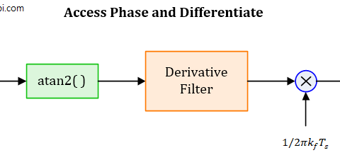
The problem here is that the argument function $\mathrm{arg}\{\cdot\}$ used in Eq (\ref{eqArg}) delivers the principal value of the argument which is highly non-linear and an unwrapping process would be needed. This becomes difficult as noise does not translate nicely from arguments to a linear representation and severely limits the performance at moderate to low SNRs. You might also find this article on how to demodulate a CQPSK signal using a C4FM receiver useful in this context.

timing recovery does not work with this scheme. The timing recoveries use interpolation using a polynomial filter which does not work with square like waves.
You’re right matt if the demod output consists of nice square waves as I plotted above for demonstration purpose. But most FSK systems do not produce such perfect square waves. A timing sync algorithm would work well with peaks at symbol centers at the input. The discussion and comments in this link might also help you. https://dsp.stackexchange.com/questions/67107/symbol-synchronization-for-gfsk-fsk-signals-in-gnu-radio
IMHO edge of the passband lies at 900 Hz because there is cut-off frequency. I don’t know why you subtracted 900 – 300 where 300 Hz means transition width. Is it a typo or I did grasp something?
Thanks for pointing that out. We talk about passband and stopband frequencies in digital filters while the cutoff frequency is more used in analog filters. The cutoff frequency in firdes.low_pass() is meant to be at the center of transition band, i.e. it should be 900-300/2=750 Hz here.
Can you please make clear the differences between passband and baseband FSK with and without IQ in a tutorial using GNU radio with coherent and non-coherent demodulation?
Also, can you make a sample DS-SS and Freq hopping spread spectrum GNU radio examples and tutorial? Do we need to create some new blocks or existing will work?
You will have to create your own flowgraphs using many of the available blocks.
Hello! There was a need to demodulate a 4-FSK signal. I don’t understand how to do this. I will be glad for any help
Use a Quadrature Demod block to change FSK into a linear scheme and then apply PSK/QAM demodulation techniques to detect the bits. There are plenty of articles on this website on how to accomplish this goal.
But the Quadrature Demod block will not help cope with 4-FSK. Or I’m wrong?
It is just an argument block. If the argument has four levels, it should not matter.
Can you help me? I will be very grateful. Where can I write to you?
You can ask me questions here. Thank you
I’m also trying to decode a 4-FSK signal. It’s also GMSK so I guess i can use QAM here as you are saying?
This is known as ACSES II or Amtrak’s PTC system. Everything I read indicates that this is not encrypted which makes sense because this is a highly cross-compatible system. Each frame is 125ms at what I gather is 4800 baud/sec and 9600 bit/sec, so 2 bits per symbol. I successfully get an unambiguous, high amplitude circle during the signal period when I go straight from decimation and re-centering to constellation sink.
I’ve tried a quadrature demod (gnuradio block) and plugged it into a wav file sink. Images:
https://ia600301.us.archive.org/23/items/acses_II_2024-04-18/2024-06-aa-1.png
https://ia600301.us.archive.org/23/items/acses_II_2024-04-18/2024-06-aa-2.png
As you can see, and in every frame, I see an approximately 40-bit bit sync (expected if it’s following ATCS specification 200 which was claimed) with the wavy part at the beginning. In this specific message, it would appear to be mostly empty with maybe some integrity checks at the end of the frame. I also noticed the quadrature demod is exactly the same output if I capture the signal with an SDR and record FM audio with GQRX. What can I learn from this demodulated output waveform? Is everything I said consistent and is my understanding correct?
Is QAM demod (gnuradio block) one way to do this? I’m not so confident I have the correct output just yet and want to confirm I’m going down the correct path.
Finally, please help me understand something. Is the constellation diagram (remember: perfect circle, points uniformly around the radius, with only a little deviation from the average radius) showing me actual symbol locations or is the actual information derived from the change in angle (AKA derivative, AKA the quadrature component?) between successive samples or something? How does this relate to the demodulation pictured above?
Thanks for asking. I wish I could help you here but your problems are many and they require a more thorough study involving much time and effort, more akin to a consulting assignment. But I hope that some other articles on this website might be able to send you in the right direction. All the best.
Didn’t see a reply button but thank you.
When executing the flow graph with the provided FSK example, there are discrepancies between the message signal and the received signal bits, resulting in errors.
Your flowgraph needs to be debugged. Many of the issues in a GNU Radio flowgraph arise from an incorrect setting of parameters in some block.
How can I contact, email, please is it for a project?