Minimum Shift Keying (MSK) is a versatile and spectrally efficient digital modulation scheme. On this website, I have previously written a tutorial on MSK in some detail. We saw how MSK is a special case of Continuous-Phase Frequency Shift Keying (CPFSK) which is a special case of Continuous-Phase Modulation (CPM). We also explored how it can also be cast as Offset Quadrature Phase Shift Keying (OQPSK).
In designing a real communication system, the design of modulators and demodulators is the easy part. The main difficulty arises from acquiring synchronization with the incoming signal. Today we investigate the carrier and timing recovery problems in an MKS modem.
Carrier Synchronization
In Chapter 7 of Wireless Communications from the Ground Up, we have described in great detail the effect of squaring on a digitally modulated signal. When such a squaring technique is applied to an MSK signal, it produces two strong spectral components at twice the modulation frequencies. Let us find out how.
Reproduce Eq (5) from MSK tutorial first.
\[
s(t) = \cos \left[2\pi F_c t + 2\pi \frac{a_n R_b}{4} t + \Theta_n\right]
\]
Since $R_b=1/T$ and modulation symbols $a_n=\pm 1$, we have
\[
s(t) = \cos \left[2\pi F_c t \pm \frac{\pi t}{2T} + \Theta_n\right]
\]
Let us denote the two frequencies as below.
\begin{align*}
f_+ =& ~F_c+\frac{1}{4T}\\
f_- =& ~F_c-\frac{1}{4T}
\end{align*}
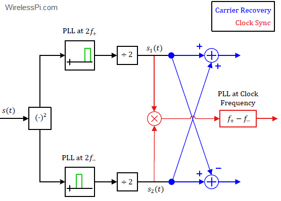
The block diagram of the synchronization circuit is now drawn below.

While the above block diagram looks complicated, we now describe how it leads to a straightforward synchronization procedure.
Squaring the signal $s(t)$ above and using the identity $\cos^2\theta = 1/2(1+\cos 2\theta)$ yields
\begin{align*}
s^2(t) =&~ \cos^2 \left[2\pi F_c t \pm \frac{\pi t}{2T} + \Theta_n\right] \\
=& ~\frac{1}{2}+\frac{1}{2}\cos \left[4\pi F_c t \pm \frac{\pi t}{T} + 2\Theta_n\right]\\
=& ~\frac{1}{2}+\frac{1}{2}\cos \left[4\pi F_c t \pm \frac{\pi t}{T}\right]
\end{align*}
because $2\Theta_n=0$ or $2\pi$, see Eq (7) in the same MSK tutorial. Clearly, the two frequencies in the above expression are $2f_+$ and $2f_-$.
\[
s^2(t) = \frac{1}{2}+\frac{1}{2}\cos \left[2\pi \left\{\underbrace{2F_c \pm \frac{1}{2T}}_{2f_+ ~\text{and}~ 2f_-}\right\}t\right]
\]
Now it is possible to lock onto each frequency through a Phase Locked Loop (PLL) and then divide the frequency of the PLL output by two. Therefore, the division by two shown in the above figure is not for the amplitude, it is for the frequency. The PLLs filter out the DC terms too.
\begin{align*}
s_1(t) =&~ \frac{1}{2}\cos \left(2\pi F_ct ~+ \frac{\pi t}{2T}\right)\\
s_2(t) =&~ \frac{1}{2}\cos \left(2\pi F_ct ~- \frac{\pi t}{2T}\right)
\end{align*}
Using the sum identity of cosines $\cos A + \cos B$ $=$ $2\cos \frac{A+B}{2}\cos \frac{A-B}{2}$, we have the sum in the upper arm.
\[
s_1(t) + s_2(t) = \cos \left(\frac{\pi t}{2T}\right)\cos \left(2\pi F_c t\right)
\]
Similarly, the difference appears in the lower arm as
\[
s_1(t) ~- s_2(t) = \sin \left(\frac{\pi t}{2T}\right)\sin \left(2\pi F_c t\right)
\]
where we have used the identity $\cos A – \cos B$ $=$ $2\sin \frac{A+B}{2}\sin \frac{A-B}{2}$. These are the carrier references required in the upper and lower arms of the O-QPSK version of the MSK demodulator! These are shown through the blue part of the block diagram of the synchronization circuit.
Timing Synchronization
To produce the desired clock, let us multiply $s_1(t)$ with $s_2(t)$ and use the identity $2\cos A \cos B$ $=$ $\cos (A-B) + \cos (A+B)$.
\begin{align*}
s_1(t)\cdot s_2(t) =&~ \frac{1}{2}\cos \left(2\pi F_ct + \frac{\pi t}{2T}\right)\cdot \frac{1}{2}\cos \left(2\pi F_ct ~- \frac{\pi t}{2T}\right) \\
\propto&~\cos \frac{\pi t}{T} + \cos 2\pi (2F_c) t
\end{align*}
The double frequency term is filtered out by the timing PLL while the remaining term can be written as
\[
\cos \frac{\pi t}{T} = \cos 2\pi\frac{1}{2T}t
\]
This is the desired clock signal at half the bit rate $1/T$. This is the rate exhibited by the MSK modulated waveform.
Concluding Remarks
Some remarks are as below.
- Being a versatile modulation, there are several types of MSK modulators and demodulators. For example, in one particular type of demodulator, the double frequency term in the last equation above can also be used for carrier recovery (although a divided by two operation for frequency is required).
- Due to the squaring operation, there is a $180^\circ$ phase ambiguity. This can be overcome by differential encoding of the data stream and differential decoding at the receive side.
I am researching UWB software receiver. I am interested in the synchronization part at the moment. Are there any specific differences when applying narrowband algorithms to UWB? Thanks in advance.
The choice of synchronization algorithms depends on system design and the designer’s preferences. There are no clear rules.
– As a general guideline, time synchronization needs to be much tighter due to short symbol time (or deterioration over a large bandwidth).
– On the other hand, frequency synchronization can be a little relaxed as compared to narrowband systems due to the fractional offset being a small part of a wide bandwidth (or little deterioration from frequency offset over a short symbol interval).
Hi Qasim, really cool stuff here especially for me as a beginner. I have a question how would I demodulate a MKS signal which was already demodulated by simply FM demodulation and asy saved as wav. I understand with FSK we would have the low and hight freq now in the amplitude and I can just look at the signal knowing the sample rate recover the bit stream. Could u push me in the right direction for MSK?
If the signal stream is already demodulated by FSK demod, you don’t need anything else. Applying coherent techniques like carrier synchronization above will give you better performance though. If you’re looking into that direction, a book titled Digital Modulation Techniques by Fuqin Xiong contains several algorithms for MSK.
Thanks for the book hint, definitely gonna look into. Still not really clear to me how I can recover the bitstream from a FM demodulated MSK signal. So I have basicaly the baseband after the Fm demodulation is that correct? But maybe I just need to look deeper into the topic. Thanks anyways!
No, that is not correct. As you suggested yourself, you need to clarify the baseband and demodulation concepts. I’m sure you will learn quickly and solve your problem. All the best.
Hallo, very nice write up, I have one question: MSK can be understood as OQPSK or (and?) CP-BFSK. For CP-BFSK, the bits are still stored in freq1 and freq2 as it looks in Figure 4 of MSK tutorial and I could decode a signal just like I would with normal BFSK where the phase between the frequency changes is not continuous whereas for MSK as OQPSK I could not.
Hi Tim, can you please rephrase the question? I did not understand it. Thanks
Hello Qasim,
Thank you for another very good write-up. I have two questions though.
The way I understand the squaring operation is that it doesn’t remove the effect of modulation, since the $\pm$ is basically a substitute for $a_n$. Is that correct? In that case the frequency components at $2f_{+}$ and $2f_{-}$ wouldn’t be constant right, but more like alternating depending on the value of $a_n$?
For the second question, I am trying to reproduce your method with some received MSK modulated data. Since this data is received by a software defined radio this data is in complex form, would you recommend to use PLL with complex signals?
Thanks in advance?
PS: A third question which may be a bit dumb, but how would you recommend implementing the frequency division by a factor 2?
– It depends on the modulation. For an amplitude modulated signal, a squaring operation does get rid of the modulation. This is, however, a frequency modulated system and hence the two signals will still have two different frequencies depending on $a_n$.
– Yes, a PLL can be used with complex signals. There are a few modifications as compared to a real signal, see Chapter 4 of my wireless communications book for an example.
– If it was an amplitude, a simple right shift by 2 would have done it. But for frequency halving, no extra PLLs are required (as opposed to going from a lower frequency to a higher frequency). All you need is a 2-bit counter and use the upper bit as the output for example.
Thank you for your quick response! (and thank you for fixing my horrible Latex markup 😉 )
My question with respect to squaring the signal was actually in relation to this modulation type specifically. Say I try to lock a PLL on $2f_+$, but that carrier switches on or off depending on the value of $a_n$, will it (obtain or retain its) lock properly?
As for the halving the frequency using a counter, am I correct to understand in that this approach you actually half the sample rate at the output?
– Yes the loop SNR will not be as good as a continuous sinusoid at frequency $2f_+$ but it will lock nonetheless.
– It depends. Halving the frequency is in general independent of sample rate.