Frequency domain beamforming implements a procedure for broadband signals that resembles the conventional narrowband beamformers

Beamforming for Broadband Signals

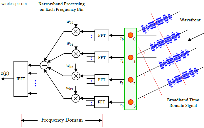
Recall that classical or physical beamforming is based on calculating the differences in wave arrival times of a signal between antenna array elements and compensating for these delays through signal processing techniques that steer the beams in any desired direction. There are two main candidates for this purpose: Phase shifting and True Time Delays (TTD). We saw in that article on beamforming that phase shifts implemented through a set of complex multipliers are incapable of beamforming over the entire bandwidth of a signal. Why? The intuitive reason is clear from a signal level view. In the narrowband scenario, the same

Continue reading
S-curve for decision-directed maximum likelihood phase error detector

What are Cycle Slips and Hangup in Phase Locked Loops?

In a previous article, we have covered in detail the inner workings of a Phase Locked Loop (PLL) in a Software Defined Radio (SDR). There are two phenomena that have the potential to occasionally disrupt the performance of a PLL operating in steady state: cycle slips and hangup. Both the carrier and timing locked loops suffer from these issues. The underlying mathematics is quite intricate and hence I give a simple overview of these concepts. A reader interested in further exploration is referred to [1]. Cycle Slips To understand the cycle slip, assume that the loop is in tracking mode,

Continue reading
An increasing degree of polynomial approximation takes the filter closer and closer to an ideal sinc impulse response

Interpolation in Digital Communication Receivers

Timing synchronization in a digital receiver is about finding the right symbol peak and the symbol rate at which digital samples are taken for decisions purpose in a constellation diagram. In general, interpolation is the process of reproducing a missing sample at a desired location. In digital and wireless communications, the role of interpolation can be explained as follows. Background Imagine a Tx signal constructed from the upsampled and pulse shaped modulation symbols. The job of the Rx is to sample this waveform at optimal intervals, i.e., exactly at the middle of the eye diagram. In other words, the Rx

Continue reading
A symbolic representation of aligning the Tx weights and Rx weights according to the channel conditions for maximum throughput

Singular Value Decomposition (SVD) – A Tutorial with an Application to Wireless Systems

Singular Value Decomposition (SVD) is a powerful concept in linear algebra whose relevance has significantly increased in recent times. Some of the notable examples are its applications in machine learning, data science and wireless communication systems. In this tutorial, I will explain the logic behind SVD from a non-mathematical viewpoint using a wireless application that forms the backbone of high speed wireless systems such as WiFi, 4G and 5G. What is Orthogonality and Why We Like It Orthogonality is a concept that comes with heavy mathematical details. However, it can be explained in a simple and non-rigorous manner. Look at

Continue reading
Block diagram of a pulse amplitude modulator and demodulator

Pulse Amplitude Modulation (PAM)

In the article on modulation – from numbers to signals, we said that the Pulse Amplitude Modulation (PAM) is an amplitude scaling of the pulse $p(nT_S)$ according to the symbol value. What happens when this process of scaling the pulse amplitude by symbols is repeated for every symbol during each interval $T_M$? Clearly, a series of bits $b$ (1010 in our initial example) can be transmitted by choosing a rectangular pulse and scaling it with appropriate symbols. \begin{equation*} \begin{aligned} m = 0 \quad b = 1 \quad a[0] = +A \\ m = 1 \quad b = 0 \quad a[1]

Continue reading