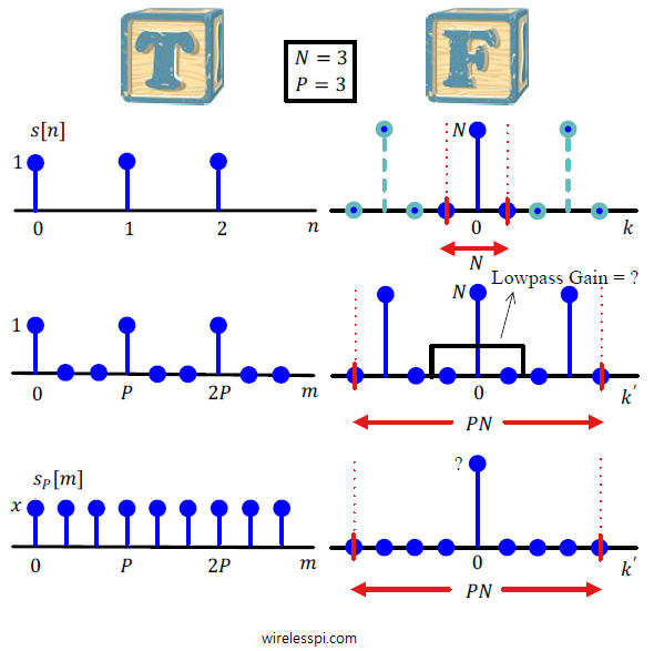
A rectangular signal and its upsampled version in time and frequency domains

Sample Rate Conversion

In the discussion on sampling, the process of sampling a continuous-time signal was discussed in detail and subsequently sampling theorem was derived. In many applications, resampling an already digitized signal is mandatory for an efficient system design. In wireless communications, sample rate conversion is utilized for upconversion and downconversion to a desired frequency, filtering stages in the digital frontend and sometimes for carrier and timing synchronization during signal acquisition. See the Cascade Integrator Comb (CIC) filters for how to accomplish this task with minimal resources. In discrete domain, sample rate can be reduced by discarding intermediate samples periodically called downsampling

Continue reading
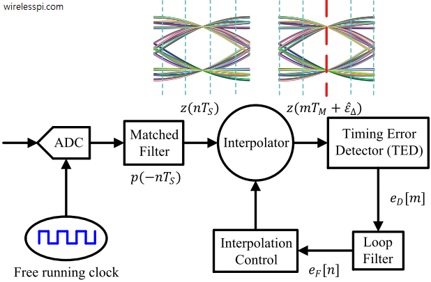
A Phase Locked Loop (PLL) for digital symbol timing recovery

Phase Locked Loop (PLL) for Symbol Timing Recovery

A Phase Locked Loop (PLL) is a device used to synchronize a periodic waveform with a reference periodic waveform. It is an automatic control system in which the phase of the output signal is locked to the phase of the input reference signal. In the context of carrier phase synchronization, we talk about tracking the phase of an input reference sinusoid. For carrier frequency synchronization, a Frequency Locked Loop (FLL) is implemented. For the purpose of timing synchronization, the target is to adjust the timing phase of a receiver clock to that of the transmitter clock such that one sample/symbol

Continue reading
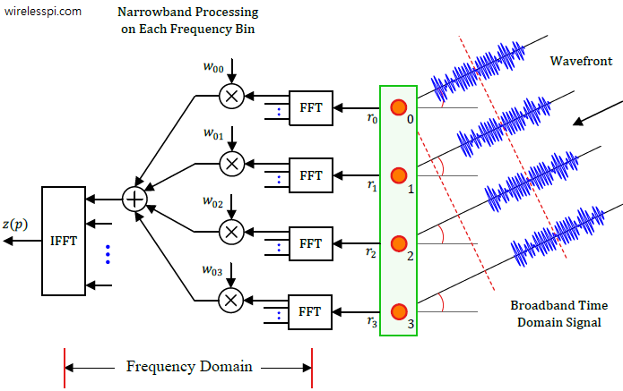
Frequency domain beamforming implements a procedure for broadband signals that resembles the conventional narrowband beamformers

Beamforming for Broadband Signals

Recall that classical or physical beamforming is based on calculating the differences in wave arrival times of a signal between antenna array elements and compensating for these delays through signal processing techniques that steer the beams in any desired direction. There are two main candidates for this purpose: Phase shifting and True Time Delays (TTD). We saw in that article on beamforming that phase shifts implemented through a set of complex multipliers are incapable of beamforming over the entire bandwidth of a signal. Why? The intuitive reason is clear from a signal level view. In the narrowband scenario, the same

Continue reading
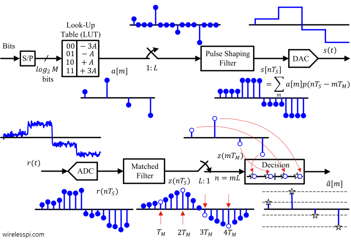
Block diagram of a pulse amplitude modulator and demodulator

Pulse Amplitude Modulation (PAM)

In the article on modulation – from numbers to signals, we said that the Pulse Amplitude Modulation (PAM) is an amplitude scaling of the pulse $p(nT_S)$ according to the symbol value. What happens when this process of scaling the pulse amplitude by symbols is repeated for every symbol during each interval $T_M$? Clearly, a series of bits $b$ (1010 in our initial example) can be transmitted by choosing a rectangular pulse and scaling it with appropriate symbols. \begin{equation*} \begin{aligned} m = 0 \quad b = 1 \quad a[0] = +A \\ m = 1 \quad b = 0 \quad a[1]

Continue reading
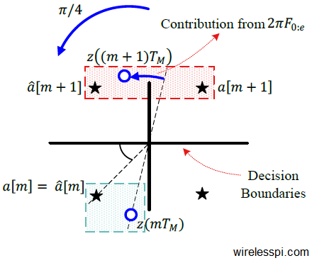
Minimum distance rule based detector decisions in a QPSK constellation in the presence of a carrier frequency offset

How a Frequency Locked Loop (FLL) Works

We saw before how a carrier frequency offset distorts the received signal. Later, we also described the classification of frequency synchronization techniques according to the availability of the symbol timing. Today, we will learn about the workings of a frequency locked loop. Background A Phase Locked Loop (PLL) is a device used to synchronize a periodic waveform with a reference periodic waveform. It is an automatic control system in which the phase of the output signal is locked to the phase of the input reference signal. In the article referred above, we also discussed that for a very small frequency

Continue reading