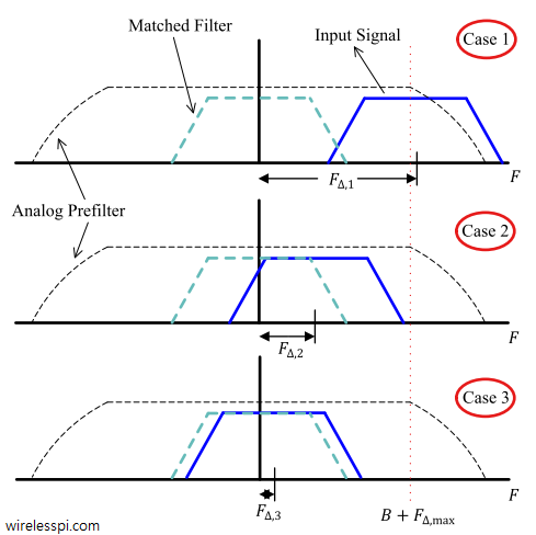
Three different cases for carrier frequency offset

What is Carrier Frequency Offset (CFO) and How It Distorts the Rx Symbols

In Physics, frequency in units of Hz is defined as the number of cycles per unit time. Angular frequency is the rate of change of phase of a sinusoidal waveform with units of radians/second. \begin{equation*} 2\pi f = \frac{\Delta \theta}{\Delta t} \end{equation*} where $\Delta\theta$ and $\Delta t$ are the changes in phase and time, respectively. A Carrier Frequency Offset (CFO) usually arises due to two reasons. The video below also explains this concept. [Frequency mismatch between the Tx and Rx oscillators] No two devices are the same and there is always some difference between the manufacturer’s nominal specification and the

Continue reading
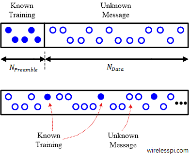
Known training sequence (a preamble) is prepended, or training can also be inserted periodically within the message

Basics of Synchronization

In every digital communication system, the Tx has the easier role of signal generation while the Rx has the tougher job of figuring out the intended message. Just like solving a puzzle told by someone. Estimating and compensating for the frequency, phase and timing offsets between Tx and Rx oscillators is one such challenge. The solution can be designed depending on many factors such as some part of data is known (called a ‘training sequence’) or not, the synchronizer needs to be one-shot or continuously updating, and so on. Known Data Availability Depending on the availability of known data, synchronization

Continue reading
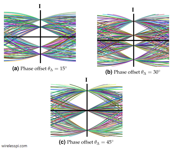
Eye diagrams for I arm of a 4-QAM signal for 15, 30 and 45 degrees phase offsets and a Raised Cosine filter with excess bandwidth 0.5. A similar eye diagram exists for Q arm as well

What is Carrier Phase Offset and How It Affects the Symbol Detection

In case of Quadrature Amplitude Modulation (QAM) and other passband modulation schemes, Rx has no information about carrier phase of the Tx oscillator. Let us explore what impact this has on the demodulation process. Constellation Rotation To see the effect of the carrier phase offset, consider that a transmitted passband signal consists of two PAM waveforms in $I$ and $Q$ arms denoted by $v_I(t)$ and $v_Q(t)$ respectively and combined as \begin{equation}\label{eqRealWorldQAMPhaseOffset} s(t) = v_I(t) \sqrt{2} \cos 2\pi F_C t – v_Q(t) \sqrt{2}\sin 2\pi F_C t \end{equation} Here, $F_C$ is the carrier frequency and $v_I(t)$ and $v_Q(t)$ are the continuous versions

Continue reading
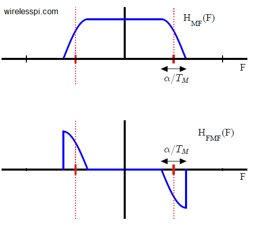
A matched filter in continuous frequency domain along with the corresponding frequency matched filter for excess bandwidth 0.25

Band Edge Filters for Carrier and Timing Synchronization

Band edge filters for carrier frequency and symbol timing synchronization is a very interesting topic that elegantly relates the tool (DSP) to the application (SDR design). This article is a short summary of where they originate from and what role they play for synchronization purpose. A Carrier Frequency Offset (CFO) arises due to a mismatch between Tx and Rx local oscillators as well as a phenomenon known as Doppler effect. In some other articles on this website, you will also find information on the Phase Locked Loop (PLL) in the context of carrier phase and timing synchronization. There is another

Continue reading
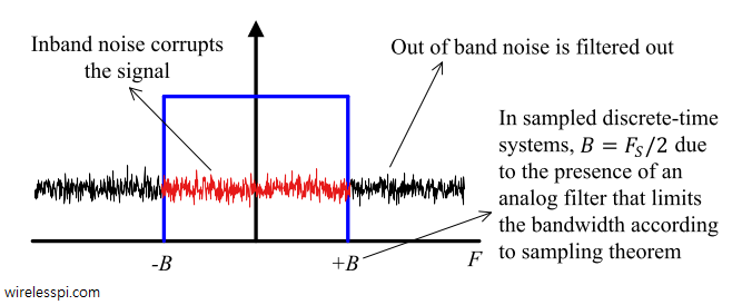
Computing noise power within a specified bandwidth

Additive White Gaussian Noise (AWGN)

The performance of a digital communication system is quantified by the probability of bit detection errors in the presence of thermal noise. In the context of wireless communications, the main source of thermal noise is addition of random signals arising from the vibration of atoms in the receiver electronics. You can also watch the video below. The term additive white Gaussian noise (AWGN) originates due to the following reasons: [Additive] The noise is additive, i.e., the received signal is equal to the transmitted signal plus noise. This gives the most widely used equality in communication systems. \begin{equation}\label{eqIntroductionAWGNadditive} r(t) = s(t)

Continue reading