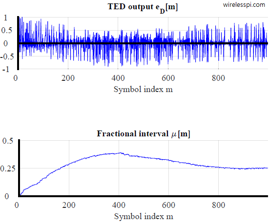
A timing locked loop with a Gardner TED converging to the steady state value for a square-root raised cosine pulse with excess bandwidth 0.4

Gardner Timing Error Detector: A Non-Data-Aided Version of Zero-Crossing Timing Error Detectors

Timing synchronization plays the role of the heart of a digital communication system. We have already seen how a timing locked loop, commonly known as symbol timing PLL, works where I explained the intuition behind the maximum likelihood Timing Error Detector (TED). A simplified version of maximum likelihood TED, known as Early-Late Timing Error Detector, was also covered before. Today we discuss a different timing synchronization philosophy that is based on zero-crossing principle. It is commonly known as Gardner timing recovery. Background Before we start this topic, I recommend that you read about Pulse Amplitude Modulation (PAM) for an introduction

Continue reading
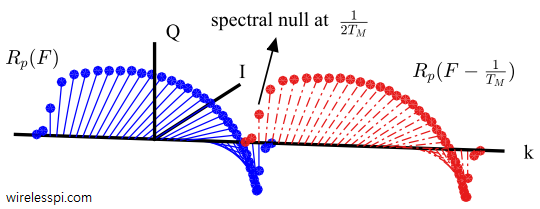
Spectrum of the Nyquist pulse and its symbol rate shifted version exhibit a spectral null at 0.5 symbol rate for a 0.5 timing offset

What is a Symbol Timing Offset and How It Distorts the Rx Signal

Timing synchronization is one of the most fascinating topics in the field of digital communications. On the bright side, numerous scientists have contributed towards its body of knowledge due to its crucial role in the successful implementation of communication and storage systems. On the not-so-bright side, this knowledge has grown to an extent that it has also become the least understood and puzzling topic in the grand scheme of things. My objective in this article is to simplify the problem in a clear and intelligible manner, and also refer to some of the most widely used solutions within the explanation.

Continue reading
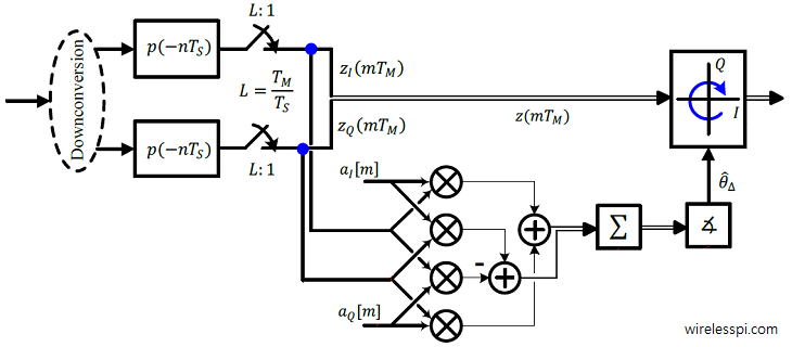
A block diagram for the implementation of the feedforward phase estimator

How to Estimate the Carrier Phase

In this article, I will describe how to estimate the carrier phase from an incoming waveform in a feedforward manner. This algorithm utilizes a sequence of known pilot symbols embedded within the signal along with the unknown data symbols. Such a signal is sent over a link in the form of separate packets in burst mode wireless communications. In most such applications with short packets, the phase offset $\theta_\Delta$ remains constant throughout the duration of the packet and a single shot estimator is enough for its compensation. Here, the primary task of the designer is to develop this closed-form expression

Continue reading
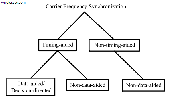
Classification of carrier frequency synchronization algorithms

Classification of Carrier Frequency Synchronization Techniques

We have discussed before that carrier phase synchronization is done at the end of the Rx signal processing chain due to the very nature of the DSP implementation. And that almost all DSP based phase synchronization algorithms are timing-aided. Timing acquisition implies knowing the symbol boundaries in the Rx sampled waveform which is equivalent to identifying the optimal sampling instants where the eye opening is maximum and Inter-Symbol Interference (ISI) from the neighbouring symbols is zero. In the case of Carrier Frequency Synchronization (CFO), this is not true. From a previous post on the effect of CFO, we know that

Continue reading
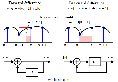
A discrete-time integrator implemented through a forward difference and a backward difference technique

Discrete-Time Integrators

An integrator is a very important filter that proves useful in implementation of many blocks of a communication receiver such as symbol timing synchronization and Phase-Locked Loop (PLL). It is an inverse operation to a differentiator that is also used in many signal processing applications such as FM demodulation and image processing. In continuous-time case, an integrator finds the area under the curve of a signal amplitude. A discrete-time system deals with just the signal samples and hence a discrete-time integrator serves the purpose of collecting a running sum of past samples for an input signal. Looking at an infinitesimally

Continue reading