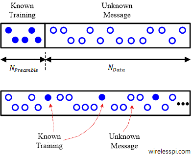
A matched filter in continuous frequency domain along with the corresponding frequency matched filter for excess bandwidth 0.25

Band Edge Filters for Carrier and Timing Synchronization

Band edge filters for carrier frequency and symbol timing synchronization is a very interesting topic that elegantly relates the tool (DSP) to the application (SDR design). This article is a short summary of where they originate from and what role they play for synchronization purpose. A Carrier Frequency Offset (CFO) arises due to a mismatch between Tx and Rx local oscillators as well as a phenomenon known as Doppler effect. In some other articles on this website, you will also find information on the Phase Locked Loop (PLL) in the context of carrier phase and timing synchronization. There is another

Continue reading

Converting Spatial Diversity into Time and Frequency Diversity

We have seen before that diversity implies using two or more statistically independent replicas for the transfer of the same information. This improves the reliability of the received message because nothing can recover the data signal in a deep fade except getting more copies of the same message. Spatial diversity has also been discussed in the context of multiple antenna systems. In this article, we describe how this diversity arising from the presence of multiple antennas can be converted into time or frequency diversity. Delay diversity converts spatial diversity into frequency diversity Phase-roll diversity converts spatial diversity into time diversity

Continue reading
Time and frequency response of a lowpass FIR filter designed with Parks-McClellan algorithm for N=33

Finite Impulse Response (FIR) Filters

We learned in the concept of frequency that most signals of practical interest can be considered as a sum of complex sinusoids oscillating at different frequencies. The amplitudes and phases of these sinusoids shape the frequency contents of that signal and are drawn through magnitude response and phase response, respectively. In DSP, a regular goal is to modify these frequency contents of an input signal to obtain a desired representation at the output. This operation is called filtering and it is the most fundamental function in the whole field of DSP. It is possible to design a system, or filter,

Continue reading
Analog beamforming

What is the Difference between Analog, Digital and Hybrid Beamforming?

Beamforming is one of the most practical solutions to overcome higher path loss and atmospheric attenuation in mmWave bands. How it is implemented is a matter of great interest to RF industry due to the conflicting requirements of efficiency and flexibility. In a tradeoff between cost, size and complexity, analog beamforming is combined with digital beamforming to give rise to a hybrid solution, an architecture of choice in current 5G mmWave systems. Nevertheless, digital beamforming is inevitably the direction of future and it is only a matter of time before it will be used in 5G networks in high bands

Continue reading
DFT-Precoded OFDM block diagram

DFT-Precoded OFDM

One of the drawbacks of an OFDM waveform is its high Peak to Average Power Ratio (PAPR). This high PAPR arises from the fact that a set of $N$ QAM symbols are taken into time domain through an inverse Fourier Transform (iFFT) operation that basically generates a combination of complex sinusoids scaled by those symbols. Due to the variations between the symbol values and the sinusoids with different frequencies, the output waveform can have a large variance in amplitudes. This reduces the power amplifier efficiency that results in faster battery drainage in a mobile terminal. The effect on base station

Continue reading