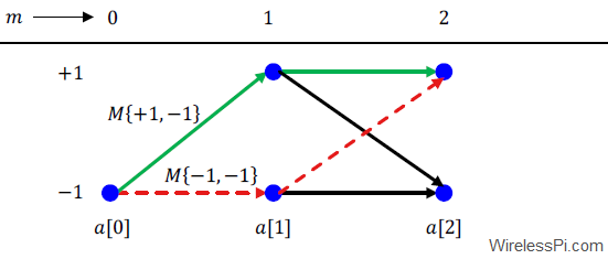
MSK as a special case of both non-linear and linear modulation schemes

Minimum Shift Keying (MSK) – A Tutorial

Minimum Shift Keying (MSK) is one of the most spectrally efficient modulation schemes available. Due to its constant envelope, it is resilient to non-linear distortion and was therefore chosen as the modulation technique for the GSM cell phone standard. MSK is a special case of Continuous-Phase Frequency Shift Keying (CPFSK) which is a special case of a general class of modulation schemes known as Continuous-Phase Modulation (CPM). It is worth noting that CPM (and hence CPFSK) is a non-linear modulation and hence by extension MSK is a non-linear modulation as well. Nevertheless, it can also be cast as a linear

Continue reading
Due to a Sampling Clock Offset (SCO), a fast Rx clock collects extra samples

Effect of Sampling Clock Offset on a Single-Carrier Waveform

We have discussed before the distortion caused by a symbol timing offset on the communication waveform. We have also derived a maximum likelihood estimate of the clock phase offset. In this article, we describe the impact of a sampling clock offset in a single-carrier waveform, also commonly known as a clock frequency offset or timing drift. A clock frequency offset is defined as the rate mismatch between the Tx and Rx clocks. Just like a carrier phase and frequency offset, the clock used to sample the incoming continuous-time signal at a rate $T_S=1/F_S$ contains a phase and frequency offset as

Continue reading
All symbol intervals are overlayed on top of one another and the time axis is shifted to bring ideal sampling instant in the middle. Eye diagram generated for 250 2-PAM symbols and Square-Root Raised Cosine pulse with excess bandwidth 0.5

Tools for Signal Diagnosis

In this article, we will devise some tools that help us diagnose problems with the communication system under study. I like to call them the stethoscopes for a communication system due to the crucial functionality they provide regarding the health of the communication system being analyzed. We discuss three such tools, namely an eye diagram, a transition diagram and a scatter plot below. Eye Diagram An eye diagram is an excellent summary of the signal behaviour in time domain, something analogous to a spectrum in frequency domain. Imagine the samples of the matched filter output taken at a much higher

Continue reading
A Tuned radio Frequency Receiver (TRF) selects the desired channel through a bandpass filter

Tuned Radio Frequency (TRF) Receiver

The tasks of a communications receiver to demodulate the transmitted signal begin with selecting the signal within a specific bandwidth at a desired frequency, commonly known as a particular channel. In another article, we discuss specifications for a radio receiver such as dynamic range, noise floor and sensitivity. Today we discuss an architecture used in earlier generations of radios. To avoid interference from the neighboring channels, the most straightforward approach is to filter out the spectral contents outside this channel and amplify the desired signal in one or more RF amplification stages. This was one of the earliest techniques employed

Continue reading
6G

The Arrival of 6G

Recently, IEEE Communications Society published an article “What will 6G be?” Some of the important points it highlighted are the following. More spectrum is needed for more bits: As with all new Gs, more spectrum is needed to entertain more bits 🙂 Sometimes I wonder where exactly we have made a phenomenal progress in delivering orders of magnitude higher data rates. According to Gerhard Fettweis, several bands between 100 and 300 GHz show some promise. Bits/s/$m^3$: Since the success of a company is measured in the revenue generated, and not exactly the bits delivered per second, the real focus is

Continue reading