Beamforming is one of the most practical solutions to overcome higher path loss and atmospheric attenuation in mmWave bands. How it is implemented is a matter of great interest to RF industry due to the conflicting requirements of efficiency and flexibility. In a tradeoff between cost, size and complexity, analog beamforming is combined with digital beamforming to give rise to a hybrid solution, an architecture of choice in current 5G mmWave systems. Nevertheless, digital beamforming is inevitably the direction of future and it is only a matter of time before it will be used in 5G networks in high bands too.
Analog Beamforming
Like most other technologies, beamforming in early years started as a humble analog solution that was improved gradually in multiple stages. It began with fixed phase shifters for generating beam at a single frequency. Flexibility was later incorporated through a switching architecture with several phase shifters, each for a different beam pattern. Finally, adjustable phase shifters at each antenna element were introduced to enable flexible and adaptive beams that could look into any direction.
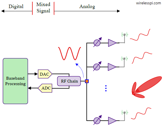
A simplified analog beamforming framework is shown in the figure below where I have prioritized a clear explanation of underlying functionality over an illustration of actual RF design. The weights are adaptively computed in digital domain and updated in analog domain using specific DSP algorithms for a target criterion.

On the Tx side, the baseband signal is generated in the digital domain that is converted into an analog signal through a Digital-to-Analog Converter (DAC), up-converted to a higher carrier frequency (e.g., 28 GHz) and then fed to an analog beamforming network through a splitter. Here, the weights are applied through several digitally controlled phase shifters, one per antenna element. Generating complicated beam patterns, e.g., in a multiuser environment, is not easy to implement through analog components. On the Rx side, the arriving signal is phase shifted at each element before combined, filtered and downconverted to baseband or intermediate frequency. Digital samples are then produced through the ADC. Since the signal has already been beamformed in the analog domain before, the sampled signal is a superposition of various waves which cannot be manipulated in digital domain.
Analog beamforming is power and cost efficient as it has only one pair of ADC, DAC and a single RF chain. However, it comes at a cost of following drawbacks.
- It is difficult to implement advanced beamforming techniques such as creating nulls in specific directions during transmit or receive. This can create significant interference among undesired directions.
- Fine tuning of the beams is limited due to the low resolution of quantized phase shifts.
- From the figure above, it is difficult to support multiple streams for multiuser MIMO. In general, a phase shifted version of the same signal is sent from all the antennas into a particular direction.
- RF phase shifters suffer from performance degradations due to losses and distortions.
All these challenges are easier to overcome through a digital beamformer.
Digital Beamforming
A simplified digital beamforming architecture is illustrated in the figure below. In this case, each antenna element has its own dedicated RF chain as well as individual DACs and ADCs. Recalling the sampling analogy, this implies that the gain and phase of each spatial sample is adjusted in an individual manner along with baseband processing before upconversion at Tx or after downconversion at Rx. This enables a true implementation of mathematical algorithms with maximum flexibility, most of which treat each antenna output as an accessible sample. For example, this flexibility is evident in the following scenarios.

- Along with maximizing the signal strength in a desired direction, nulls can also be created in undesired directions to suppress the interference.
- Multiple spatial streams can be simultaneously created for spatial multiplexing. More complicated precoders can be implemented for this purpose to generate multiple beams and enable multiuser communications. This is done by matrix multiplication in digital domain similar to the SVD decomposition.
- The beamforming weights, discussed in both physical and virtual scenarios, were for narrowband signals. A digital architecture allows for catering large bandwidths by selecting the weights for a frequency selective scenario. Wideband signal transmission and reception improves the spectral efficiency of the system by operating over a large signal bandwidth without beam squint (change in beam pattern as a function of operating frequency).
To obtain all these benefits, all spatial samples need to be individually processed. Here, each antenna element having its own frontend comes at a cost. ADCs and DACs operating at Multi-GHz clock frequencies are complex and power consuming. Consequently, fully digital beamforming is utilized in commercial multi-antenna systems in the lower frequency range while initial mmWave systems mostly utilize hybrid beamforming architectures as described next.
Hybrid Beamforming
Hybrid beamforming is a compromise between low power but less flexible analog beamforming and power hungry but fully flexible digital beamforming solutions. This two-stage architecture is drawn in the figure below where precoding or combining is done first in the analog part and later in the digital domain. While the antenna elements are still driven by analog phase shifters, the number of RF chains and ADC/DAC are lesser than the number of antennas. Precoding is then performed in the digital domain at the level of radio chains. This reduction in the number of data converters and corresponding chains results in less cost, computational load and power consumption. Multiple spatial streams can also be supported, albeit only up to the number of RF chains and hence less than what pure digital beamforming has to offer. In summary, both the digital and analog beamforming work together in this case to improve the coverage or to provide multiple beams to spatially separated users.

Analog or RF precoding/combining in the figure above can be implemented through two different schemes.
- An antenna array is divided into several subarrays, each forming an analog beamforming network and connected to its own RF chain. Since the subarrays operate more or less in an independent manner, the overall framework reduces complexity and power consumption at a cost of less flexibility. This is drawn in the left figure below.
- Each antenna is connected to all RF chains and the digitally controlled phase shifters are computed based on some jointly optimal criteria. This provides maximum flexibility in directing and manipulating multiple beams at a cost of complexity. Such an architecture is shown in the right figure below.

The weights in digital and analog domains are chosen to closely approximate the optimal solution that results in minimum interference among the streams. The optimal solution is not trivial due to the number of antennas and subarrays involved as well as additional constraints that come with choosing imprecise analog weights. A trade-off needs to be made between performance and complexity.
To see why hybrid beamforming strikes a good balance between complexity and flexibility, remember that the spatial selectivity implemented by a beamformer comes from a combination of signals generated from or arriving at individual antenna elements, each of which radiates or receives according to its own radiation pattern, irrespective of the array factor. Since each element has its own RF chain from the element down to the baseband in a digital beamformer, each of them has to accommodate both the desired and undesired signals and thus suffers from a high dynamic range (the ratio between maximum and minimum signal level). This leads to high power consumption. Now notice from the hybrid beamforming figure before that it is not being done for all antennas in the array in the hybrid solution. Instead, a set of antennas already implement analog beamforming before the signal is presented to the digital path.
As described before, things are changing fast though in this area. With advancement in data conversion technology (e.g., RF sampling ADCs and DACs) and increased level of on-chip integration, the era of an all-digital beamforming in mmWave bands is on the horizon.
Concluding Remarks
In conclusion, we covered how beamforming can be done in analog domain after the DAC at Tx side and before the ADC at Rx side. In the context of an OFDM system, this is shown within the Analog Signal Processing (ASP) block in the figure above which obviously implements other tasks related to the frontend too in addition to the phase shifting operations. In a similar manner, beamforming can also be performed in digital domain before the DAC on the Tx side or after the ADC on the Rx side, as drawn in the same figure. In practice, the case for digital beamforming gives more choices in this regard. Finally, beamforming can also be classified as time domain vs frequency domain, as explained in the case of broadband signals.