Spectrum of a sinusoid

Generating Signals and Viewing the Spectrum

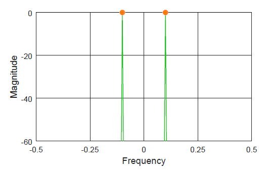
One of the most common questions DSP beginners have is how to generate the signals (particularly, sinusoids) and view their spectrum. They have a rough idea what time domain and frequency domain are about but struggle to construct the first few lines of code that open the gates towards a deeper understanding of signals. For this reason, I produce below an Octave (or Matlab) code that you can simply copy and paste to view and modify the results. Keep in mind that the code has been written for an explanation purpose, not conciseness or optimization. As you progress towards developing

Continue reading
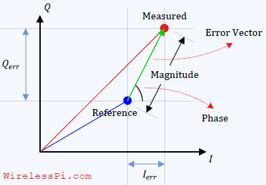
Error Vector Magnitude (EVM) for 1 symbol

What is Error Vector Magnitude (EVM)?

Measuring the performance of a digital communication system is not a straightforward task as different impairments have different impacts on the final bit error rate. Error Vector Magnitude (EVM) is a useful metric that helps gauge the impact of all impairments simultaneously from a single value. A Single Modulation Symbol We start with observing a single modulation point at the receive end. Once we establish the baseline error in this scenario, we will combine the effect of all such symbol points into a single number. Assume that a modulation symbol S is represented by a blue constellation point in the

Continue reading
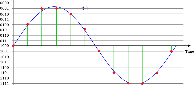
Pulse Code Modulation (PCM)

Specifications of a Radio Receiver

When designing a radio receiver, a system architect has to deal with the issues such as dynamic range, noise floor and sensitivity of a radio receiver [1]. The ultimate purpose is computing a power budget to ensure that a minimum amount of signal power is available at the receiver during operation. This is not much different than how a country assigns an available budget into different sectors such as defense, education and health. Dynamic Range Dynamic range is the ratio of the largest signal level to the smallest signal level that the system can process in analog and digital stages.

Continue reading
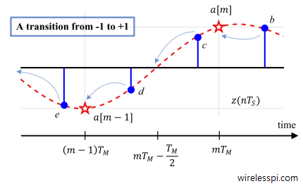
Working of an Early-Late TED

On the Link Between Gardner Timing Error Detector and Early-Late Timing Error Detector

This post is written on an advanced topic mainly for practitioners and researchers in the design of wireless systems. For learning about wireless communication systems from a DSP perspective (the idea behind SDRs), I recommend you have a look at my book. F. M. Gardner described his well known Timing Error Detector (TED) — known as Gardner TED — in his often cited article [1]. Gardner was a pioneer in the area of synchronization and Phase Locked Loops (PLL). Later, M. Oerder (a student of Heinrich Meyr) derived this scheme from the maximum likelihood principle in [2]. Heinrich Meyr is

Continue reading
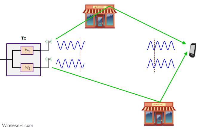
An intuitive way to understand the maximum ratio transmission

Maximum Ratio Transmission (MRT)

In Maximum Ratio Combination (MRC), our focus was on combining the signals from multiple antennas at the Rx side. Here, we will see how a similar system can be developed with multiple antennas at the Tx side. As our first consideration, we attempt to replicate the results of Rx diversity in a scenario where there are multiple Tx antennas and a single Rx antenna. This is commonly known as a Multiple-Input Single Output (MISO) system. Assume that there are $N_T$ Tx antennas available and only a single Rx antenna as shown in the figure below. This is a dual problem

Continue reading