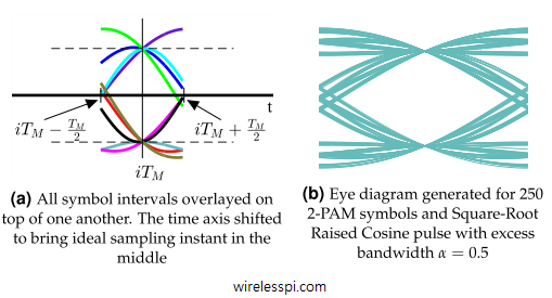
An illustration of wiping off the modulation process without any training information

Non-Data-Aided Carrier Phase Estimation

A carrier phase offset rotates the Rx constellation causing decision errors even in a perfectly noiseless environment. One of the techniques used to overcome this problem is to insert a known sequence at the start of the transmission known as a preamble. Then, the Rx can utilize these known symbols in the arriving signal to estimate the carrier phase and de-rotate the constellation. However, inserting a known sequence within the message decreases the spectral efficiency of the system. To avoid this cost, a phase estimator (as well as estimators for other distortions) can be derived in a non-data-aided fashion. One

Continue reading
Square-Root Raised Cosine (SR-RC) spectrum with different excess bandwidths

Modulation Bandwidths

From the article on pulse shaping, we can correctly determine the occupied bandwidth for each modulation scheme where the Square-Root Raised Cosine spectrum shows the bandwidth of a Square-Root Raised Cosine pulse shape as $0.5(1+\alpha)R_M$. Also, we have discussed earlier that the spectrum approximately remains the same, provided that there is enough randomness in bit stream and the resulting symbols are equally likely and independent from each other. Therefore, the bandwidth for a PAM modulated signal can be given as \begin{equation}\label{eqCommSystemBWPAM} BW_{\text{PAM}} = 0.5\left(1+\alpha\right)R_M \end{equation} QAM is basically a similar modulation scheme except that it is modulated on a carrier.

Continue reading
A rectangular signal and its upsampled version in time and frequency domains

Sample Rate Conversion

In the discussion on sampling, the process of sampling a continuous-time signal was discussed in detail and subsequently sampling theorem was derived. In many applications, resampling an already digitized signal is mandatory for an efficient system design. In wireless communications, sample rate conversion is utilized for upconversion and downconversion to a desired frequency, filtering stages in the digital frontend and sometimes for carrier and timing synchronization during signal acquisition. See the Cascade Integrator Comb (CIC) filters for how to accomplish this task with minimal resources. In discrete domain, sample rate can be reduced by discarding intermediate samples periodically called downsampling

Continue reading
A Phase Locked Loop (PLL) for digital symbol timing recovery

Phase Locked Loop (PLL) for Symbol Timing Recovery

A Phase Locked Loop (PLL) is a device used to synchronize a periodic waveform with a reference periodic waveform. It is an automatic control system in which the phase of the output signal is locked to the phase of the input reference signal. In the context of carrier phase synchronization, we talk about tracking the phase of an input reference sinusoid. For carrier frequency synchronization, a Frequency Locked Loop (FLL) is implemented. For the purpose of timing synchronization, the target is to adjust the timing phase of a receiver clock to that of the transmitter clock such that one sample/symbol

Continue reading
A signal broken down into scaled and shifted impulses

Convolution

Understanding convolution is the biggest test DSP learners face. After knowing about what a system is, its types and its impulse response, one wonders if there is any method through which an output signal of a system can be determined for a given input signal. Convolution is the answer to that question, provided that the system is linear and time-invariant (LTI). We start with real signals and LTI systems with real impulse responses. The case of complex signals and systems will be discussed later. Convolution of Real Signals Assume that we have an arbitrary signal $s[n]$. Then, $s[n]$ can be

Continue reading