![Magnitude of frequency response |H[k]| in response to complex sinusoids at all N frequencies](https://wirelesspi.com/wp-content/uploads/2016/08/figure-introduction-freq-response.png)
In wireless communications and other applications of digital signal processing, we often want to modify a generated or acquired signal. A device or algorithm that performs some prescribed operations on an input signal to generate an output signal is called a system.
In another article about transforming a signal, we saw how a signal can be scaled and time shifted, or added and multiplied with another signal. These are all examples of a system. Amplifiers in communication receivers and filters in image processing applications are some systems that we interact with in daily lives. A communication channel is also a system about which we need to learn for successful transmission of data. Our main focus in these articles will be on a particular class of systems which are linear and time-invariant.
After learning about a system, the question is: how should we characterize a system in both time and frequency domains? Impulse response is a tool to characterize a system in time domain and frequency response to do the same in frequency domain. We start with description of impulse response.
Impulse Response
As the name says it, impulse response is just the output response of a system to a unit impulse $\delta[n]$ as an input. It is a way of characterizing how a system behaves. Impulse response is also a signal sequence and it is usually denoted as $h[n]$.
As an example, when a tuning fork is hit with a rubber hammer, the response it generates is a back and forth vibration of the tines that disturb surrounding air molecules for a certain amount of time: its impulse response. In a very similar manner, when a system is `kicked’ by a unit impulse signal, the whole sequence of samples it generates can be viewed as its impulse response.
If a system delays any input signal by $3$ samples, the impulse response $h[n]$ will be $\delta[n]$ shifted by $3$ samples.
\begin{equation*}
h[n] = \delta[n-3]
\end{equation*}
Of course, impulse response $h[n]$ of a real-world system is much more complex. An example is illustrated in Figure below.
![Impulse response h[n] is system output in response to a unit impulse input](http://wirelesspi.com/wp-content/uploads/2016/08/figure-introduction-impulse-response.png)
Frequency Response
From the definition of impulse response, it is straightforward to guess that frequency response of a system is defined as the DFT of its impulse response.
\begin{align*}
h[n] &~\xrightarrow{\text{\large{F}}}~ H[k]
\end{align*}
From the DFT definition,
\begin{align}\label{eqIntroductionFreqResponse}
H_I[k]\: &= \sum \limits _{n=0} ^{N-1} h_I[n] \cos 2\pi\frac{k}{N}n + h_Q[n] \sin 2\pi\frac{k}{N}n \\
H_Q[k] &= \sum \limits _{n=0} ^{N-1} h_Q[n] \cos 2\pi\frac{ k}{N}n – h_I[n] \sin 2\pi\frac{k}{N}n
\end{align}
Remember from another article on DFT examples that DFT of an all-ones sequence is a single impulse in frequency domain. Owing to the duality of time and frequency domains, the inverse is also true: the DFT of a single impulse in time domain is an all-ones rectangular sequence in frequency domain, which is nothing but $N$ complex sinusoids of equal magnitudes.
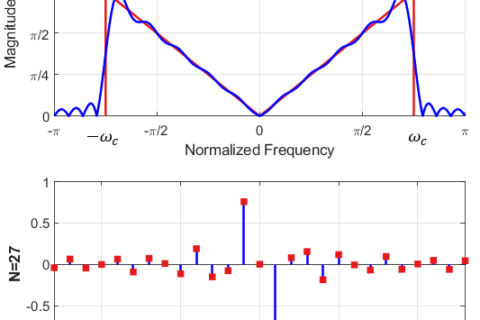
So when an impulse is input to a system in time domain, a sequence of $N$ complex sinusoids with equal magnitudes are input to the system in frequency domain. Figure below shows an example of frequency response magnitude of a system.
![Magnitude of frequency response |H[k]| in response to complex sinusoids at all N frequencies](http://wirelesspi.com/wp-content/uploads/2016/08/figure-introduction-freq-response.png)
Two questions arise at this stage:
- What happens at the output in frequency domain as a result of a complex sinusoidal input?
- In fact, any DSP learner notices a dominant use of real and complex sinusoids throughout the DSP literature. What makes such signals so significant?
We answer these questions in the discussion about convolution.