In a previous article, we have discussed in detail the free space propagation in mmWave systems. We saw that the received power at any distance is independent of the carrier frequency as long as the effective antenna aperture is taken into account. Today, we describe the role of atmospheric effects such as water vapors, oxygen, rain and penetration loss in materials that impact the signal propagation at higher carrier frequencies. Important parameters of small-scale fading in a wireless channel such as delay spread and Doppler spread are also explained in the context of mmWave systems.
Atmospheric Effects
In realistic channels, the mmWave path loss increases over and above the free space attenuation due to several frequency-dependent factors [1].
Water Vapors and Oxygen
At lower microwave frequencies, the effects of water vapors and oxygen molecules in the air can be safely ignored. This is not true for mmWave spectrum. For a reference, the figure below indicates the excess attenuation across the mmWave and sub-TeraHz spectrum at 60 GHz, 120 GHz, 180 GHz, 320 GHz and 380 GHz caused by atmospheric absorption. In particular, electromagnetic waves around 60 GHz are severely attenuated due to oxygen absorption, a phenomenon that results in more than 15 dB/km loss in Rx power. Therefore, these frequencies are suited for indoor networks with short coverage range. The remaining frequencies, e.g., around 50 GHz, 100 GHz or 150 GHz, there is very little attenuation beyond the normal free space propagation loss.

Rain
In addition to the atmospheric absorption, the weather also impacts the mmWave propagation such as rain and snow. This is because the physical size of the raindrops, hail stones and snowflakes is on the order of the propagating wavelength causing non-negligible scattering. As a consequence, the link budget needs to account for approximately 15 dB/km extra attenuation during heavy rains and is usually closed with the help of additional beamforming gains.
Penetration
Several measurement campaigns have shown that penetration into outdoor building material also suffers from losses amounting to several tens of dBs over free space loss. Therefore, it is difficult for mmWave signals to penetrate into the buildings from outside and vice versa.
There are three main mechanisms for wave propagation in a wireless channel: diffraction, scattering and reflection. Diffraction is the bending of waves around corners of the obstacles. That object or aperture effectively becomes a secondary source of the propagating wave. From the perspective of a wireless signal at microwave frequencies, waves coming from diffracting objects keep the communication link operational even when there is no line of sight between the user terminal and the base station. On the other hand, diffraction mechanism suffers from heavy losses in mmWave band as compared to other phenomena like reflections and scattering. Therefore, mmWave systems do not rely on diffraction for wave propagation and instead resort to virtual beamforming in which the Tx and Rx look for reflected and scattered paths to maximize the Rx power through array gain.
Delay Spread
As explained in the discussion on small-scale fading, the delay spread of a wireless channel is a measure of the time difference between the first and the last arriving multipath. In general, it is characterized by the symbol time of the system, i.e., the same delay spread of, say, $2~\mu$s can extend to 1 symbol or 100 symbols, depending on whether the symbol rate is $0.5$ MHz or $50$ MHz. This implies that for smaller symbol rates (i.e., larger symbol times), there is less Inter-Symbol Interference (ISI) which determines the amount of bandwidth over which the spectrum is relatively constant. This is known as a frequency flat channel. On the other hand, for larger symbol rates (i.e., lower symbol times), the multipath extends over several tens of symbols thus introducing ISI and dips in the signal spectrum. This is known as a frequency selective channel.
It turns out that there are three effects governing this behavior in mmWave channels.
- The main attraction of mmWave bands is to exploit vast unused spectrum where even several GHz of bandwidth can be committed to a single user. Since the symbol rate is directly proportional to the bandwidth, we have significantly large symbol rates or reduced symbol times in mmWave systems as compared to lower frequency bands. Such a large bandwidth (i.e., short symbol time) necessitates long delays if the multipath at mmWave frequencies follow the same pattern as the lower bands.
- As we found above, free space path loss, atmospheric absorption and penetration losses result in substantial attenuation before the signal reaches the Rx. Therefore, even within the same environment, propagation characteristics are different and multiple copies die down relatively much quicker thus reducing the delay spread.
- 4G and the previous generations of cellular systems relied on omnidirectional radiation patterns, thus opening the possibility of multiple copies arriving after reflection, scattering and diffraction from any objects around the Tx or Rx. Such a scenario naturally increases the delay spread because a multipath can arrive from any direction. In contrast, mmWave Tx and Rx in 5G systems employ highly directional antenna arrays that either `look’ into particular directions (classical beamforming) or bouncing the multipath signals off various objects for a coherent summation at the Rx (virtual beamforming). As a result of these smaller number of paths, the delay spread is further reduced. One consequence of a pointed beam as in physical beamforming and subsequent reduction in multipath spread is that the extent of equalization needed at the Rx also gets simplified.
In conclusion, the overall effect of the above phenomena is that mmWave systems suffer from smaller delay spreads and hence less frequency selective fading. In fact, frequency dependence can be significantly reduced with a massive MIMO setup since the effective channel reduces to a constant value.
Doppler Spread
From high school physics and this article, we know that there is a shift in frequency, known as Doppler shift, that arises from movement in the channel and given by
\[
F_D = -\frac{\nu}{c}F_C
\]
From the above expression, the Doppler shift depends on the carrier frequency $F_C$ and the velocity of the Rx antenna $\nu$. The relevance here is clear: the higher the frequency, the higher the Doppler shift and vice versa.
Now let us run some quick numbers for mmWave frequencies. If the user is moving at a normal walking speed of $5$ km/hr (around $1.4$ m/s) exactly in a line away from the Tx (so $\phi=\pi$) and the transmission is taking place at a carrier frequency of $F_C=60$ GHz, then the Doppler frequency turns out to be
\begin{equation*}
F_D = -\frac{1.4}{3\cdot 10^8} \cdot 60\cdot 10^9 \approx -280 ~\text{Hz}
\end{equation*}
This number will be far greater at vehicular speeds. As explained in my wireless communications book, when multiple paths undergo different Doppler shifts, the result is a phenomenon known as Doppler spread that is the frequency domain counterpart of delay spread in time domain. Just like the delay spread determines the frequency selective nature of the channel, the Doppler spread governs the time selective nature of the channel, i.e., the rate of change of the channel gains (which are assumed constant for a frame duration) depends on the Doppler spread. The exact time varying characteristics depend on the velocity, carrier frequency and the bandwidth as well as the beamwidth.
There are a few factors that help achieve a balance for this time varying effect at mmWave frequencies.
- For coherent demodulation in 5G systems as we have seen before in MIMO detection algorithms, channel gains need to be estimated at the base station. These estimates need to be updated according to how fast the channel varies with time, say, by moving 1/8th of the wavelength. As the mmWave carrier frequencies increase with a corresponding decrease in the wavelength, a significant channel variation occurs for even small movements. For the same speed, the channel varies 15 times faster at 52 GHz as compared to 3.5 GHz. Consequently, a faster rate of update is needed that demands more pilots at a cost of actual data rate penalty.
- Remember that the reason to move to higher carrier frequencies is to exploit vast bandwidths that translate into higher symbol rates and consequently shorter symbol times! This implies that there is no substantial change in the number of symbols that fit into a coherence interval.
- With narrow beams resulting in a reduced angular spread, remember that mmWave base stations serve a small number of low mobility users in a limited geographical area. This eases the stringent requirements that could have arisen with rapid channel variations.
In summary, the size of a frame with a given percentage of pilot symbols can still be kept the same. If the channel changes more rapidly, say 5 times faster, then the frame also gets transmitted in a shorter time while maintaining the same number of pilot symbols. This strategy, along with higher cell density with small low mobility users, aligns with the goals of 5G systems that aim for a lower communication latency as compared to 4G systems.
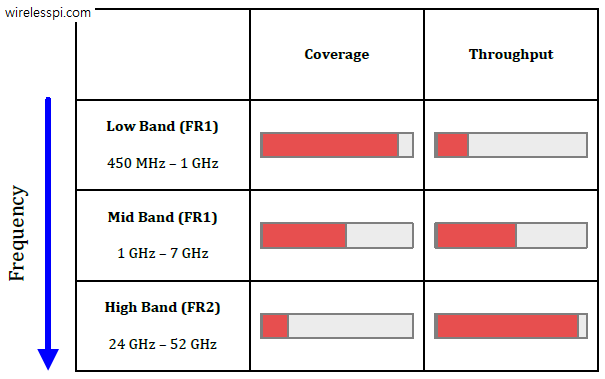
A final summary of coverage and throughput in different frequency bands is shown in the figure below. While the throughput rises with increasing frequency, the coverage shrinks due to the propagation effects discussed above. The decision on the frequency band of choice then depends on the actual deployment scenario.

References
[1] T. Rappaport, R. Heath, R. Daniels, J. Murdock, Millimeter Wave Wireless Communications, Pearson, 2014.