In the article on pulse shaping, we described the excess bandwidth, also known as roll-off factor, as the extra fractional bandwidth required to shape the spectrum. As it turns out, this excess bandwidth is also crucial for accomplishing timing synchronization in single-carrier systems due to its participation in generating spectral timing lines.
Spectral Timing Lines
Since a data stream consists of a sequence of 1s and 0s, the signal waveform is not a pure clock. Instead, a series of 1s and 0s appear in random order. The purpose of timing synchronization is to extract a clock out of this waveform. For this purpose, it is passed through a non-linearity (e.g., an absolute value operation). Let us see the implications of this idea in frequency domain first. To understand the visualizations that follow in both frequency and time, I highly recommend reading the article on pulse shaping first.
Frequency Domain View
The non-linear operation in time domain actuates a convolution in frequency domain of the signal spectrum with its replica. The resultant spectrum at $F=\pm 1/T_M$ (where $T_M$ is the symbol time) is determined by the overlap of the two spectra at the instant when the sliding spectrum reaches $\pm 1/T_M$. The image at that moment is captured in the figure below for three excess bandwidths, $\alpha = 0$, $0.5$ and $1$.

It is clear that the larger the excess bandwidth, the larger the overlap region between the two spectra and hence taller the resultant timing line. Recalling the band edge filters for frequency synchronization that exploit the excess bandwidth as well, this is the reason why you will often hear the following saying from Fred Harris.
"Excess bandwidth provides the energy required for timing and frequency synchronization."
It should be kept in mind that this is true for other timing schemes derived from the above principles too. Nevertheless, there are indeed timing error detectors that benefit from a deficiency of excess bandwidth and their performance deteriorates for higher values of excess bandwidth $\alpha$. Mueller and Muller (M&M) timing error detector is one such example.
Time Domain View
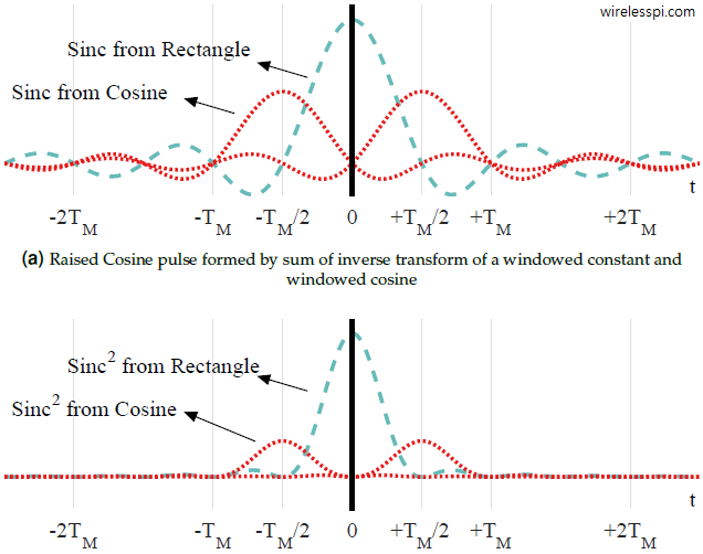
Coming back to the time domain, we explain the case for $\alpha=1$ and it is straightforward to generalize the concept for other values of $\alpha$. Recall from the discussion on pulse shaping filter that the expression for a Raised Cosine filter in frequency domain for $\alpha = 1$ is given by
\begin{align}\label{eqTimingSyncRaisedCosineAlpha1}
R_p(F) = \frac{T_M}{2} \left[1 + \cos \left(2\pi\cdot \frac{T_M}{2} \cdot|F|\right) \right] \quad -\frac{1}{T_M} \le F \le +\frac{1}{T_M}
\end{align}
There, we also covered the following steps:
- In time domain, the constant term translates to an impulse at time location $0$, and $\cos(\cdot)$ results in two impulses with half that amplitude at time locations (inverse period) $\pm T_M/2$. If you don’t know why, see the spectrum of a cosine.
- The rectangular window of width $2/T_M$ that defines its support in frequency is a sinc signal in time domain with zero crossings at integer multiples of $\pm T_M/2$.
- Convolution of a signal with an impulse is the signal itself. When convolved with sinc arising from the window, this generates three sinc signals: one at time $0$ (convolution of the above sinc with impulse from constant term) while two at time $\pm T_M/2$ (convolution of the above sinc with impulses from the cosine).
The resulting time domain signal is plotted in the first subfigure below without the cumulative signal (that is irrelevant to our discussion here). When its square is drawn in the second subfigure below (cross terms not shown), it is clear from their period that the extra sinc signals — arising from the spectral cosine responsible for excess bandwidth — provide the energy to $1/T_M$ sinusoidal signal. These additional sincs are absent for $\alpha=0$ and very small for low values of $\alpha$.

Another interesting explanation on the effect of excess bandwidth $\alpha$ in time domain is seen from the figure below that is reproduced from early-late timing error detector and plots an average squared trajectory of a binary PAM sequence filtered with a Raised Cosine filter for three different excess bandwidths: $\alpha$ $= 0, 0.5$ and $1$.
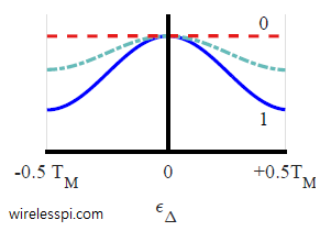
Notice that the average value for $\alpha=0$ is flat with no dependence on the timing error. Therefore, it provides no relevant information for timing synchronization. On the other hand, $\alpha=0.5$ and $\alpha=1$ provide suitable timing information due to the dependence of their average curves on the timing error. We conclude that a large excess bandwidth $\alpha$ provides a larger slope in a squared and averaged eye and hence more timing information.
Hello,
In this sentence, “It is clear that the larger the excess bandwidth, the larger the overlap region between the two spectra and hence taller the resultant timing line”:
What do you mean by “taller the resultant timing line”