Similar to the carrier lock detectors, timing lock detectors can also be constructed based on some property of the modulated signal. These lock detectors operate in parallel to the timing locked loop and aid the Rx state machine in executing necessary tasks according to each scenario. The expressions for two such timing lock detectors are as follows.
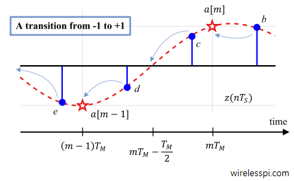
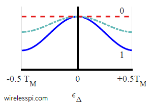
- The output of a timing lock detector should be at its peak for the correct timing. Therefore, when the matched filter output, denoted by $z(mT_M)$ with $T_M$ being the symbol time, is at its peak, the second sample in a signal oversampled by 2 should ideally cross through zero. This leads to a maximum amplitude difference between these two samples. Taking a long term average thus yields a non-data-aided strategy as
\begin{equation*}
\text{LD}(\epsilon_\Delta) = \sum_{n=0}^{2N_D-1} \Big\{\left|z (mT_M)\right|^2 – \left|z\left(mT_M-\frac{T_M}{2}\right)\right|^2 \Big\}
\end{equation*}where $\epsilon_\Delta$ is the symbol timing offset, $T_M$ is the symbol time, $L$ is the oversampling factor and $N_D$ is the sequence length. - The lock detector mentioned above suffers from the dynamic range problem due to its dependency on the Rx signal amplitude. The solution then is to normalize the lock detector output by the signal magnitude as
\begin{equation*}
\text{LD}(\epsilon_\Delta) = \sum_{n=0}^{2N_D-1} \frac{|z (mT_M)|^2 – \left|z\left(mT_M-\frac{T_M}{2}\right)\right|^2}{|z (mT_M)|^2 + \left|z\left(mT_M-\frac{T_M}{2}\right)\right|^2}
\end{equation*}
There are other possibilities too for detecting the timing lock but most of them are based on a similar principle as above.