Human eyes can only see in the visible part of the electromagnetic spectrum. Radar (Radio Detection and Ranging) is a device that extends our ability to detect the environment far beyond what is allowed by the visual nervous system, see the article on Frequency Modulated Continuous-Wave (FMCW) radars. Today we talk about the idea of pulse compression and the role it plays in target detection.
As opposed to a Continuous-Wave (CW) radar, a pulsed radar transmits a short burst of energy followed by a period of silence during which it listens for the echo received from the target. As shown in Fig 1 below, pulses of the same frequency are sent with a rectangular envelope.
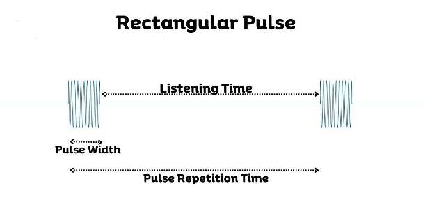 Fig 1: Transmitted rectangular pulse.
Many real pulsed radar systems do not transmit rectangular pulses. Instead, they modulate the frequency throughout the pulse using techniques like Linear Frequency Modulation (LFM). From a hardware perspective, generating an LFM pulse is more complex than producing a rectangular pulse. Thus, one might wonder why opt for LFM over a rectangular pulse.
To understand this idea, consider a rectangular pulse again.
Rectangular Pulse and Matched Filtering
As depicted in Fig 2 below, the radar receiver picks up noise and other interferences even before the echo returns. However, despite this, we are still able to detect and isolate the returned echo.
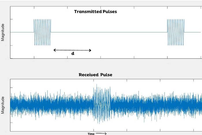 Fig 2: Transmitted and received rectangular pulses.
By calculating the time delay between the transmitted pulse and the received pulse (denoted by $d$ in Fig 2), we can accurately determine the range of the object. This is achieved through processing the received signal using a matched filter. The matched filter entails preserving a copy of the transmitted pulse and conducting correlation between this template and the received signal to determine if the known signal is present in the unknown environment. An animation for this process is drawn in Fig 3 below.
 Fig 3: Illustration of Matched Filter.
Initially, the output of the matched filter is low. As the pulse begins to correlate with the received signal, the output gradually increases. It reaches its maximum when the template aligns perfectly with the returned pulse. At this juncture, they are highly correlated as they essentially match each other. Subsequently, as this alignment shifts, the correlation between the template and the received signal starts to decline until it is completely out of the pulse.
Now, we have a processed signal that resembles a triangle rather than the rectangle we started with. This is advantageous for two reasons:
- First, the peak of the triangle helps us determine the location of the returned pulse. Identifying a peak is much simpler than pinpointing the starting point of the pulse energy.
- Second, in the presence of additive noise, the rectangular pulse becomes difficult to recognize, making it challenging to locate the start of the pulse energy. However, with a triangular pulse, it is much easier to find the peak. This is because random additive noise does not correlate well with the template and hence does not generate a peak out of the matched filter.
However, in the presence of excessive noise, as shown in Fig 4 below, the raw signal becomes heavily corrupted resulting in the matched filter output lacking a well-defined peak.
 Fig 4: Effect of noise on Matched Filter output.
This is due to the shallow nature of the triangular shape, despite it having a defined peak, which is beneficial for detection. Because of its shallow slope, it becomes more susceptible to noise interference. The noise can elevate the correlation sufficiently to generate a false peak close to the actual peak, leading to uncertainty in determining the delay.
Resolution
Furthermore, the triangle we obtain is wider than the original pulse (see Fig 5 below), which affects our ability to determine the resolution of the radar. This, in turn, impacts the effectiveness of recognizing two objects that are closely separated.
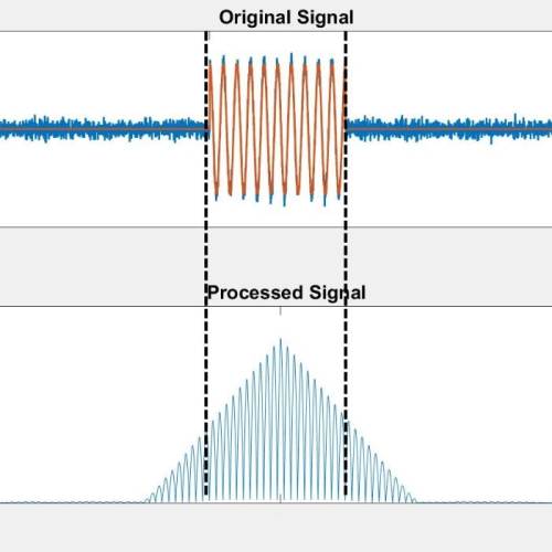 Fig 5: Pulse Widths of Original Signal and Processed Signal.
For example, consider Fig 6 below where two objects separated by some distance. When the echoes of both objects reach the radar, the matched filter determines whether the return echo has come from a single target or two separate ones. To make this distinction, the received echoes must be separated by a minimum distance.
 Fig 6: Transmission and reception of pulses.
In Fig 7 below, we observe that when sweeping the matched filter across the received signal containing two echo pulses, we first encounter a peak corresponding to the first object. Subsequently, the correlation becomes flat as the template transitions from one end of the first echo to the other end of the second echo. Then, we encounter another peak corresponding to the second echo. Therefore, if the objects are sufficiently separated, we can still distinctly detect two objects by observing their respective peaks.
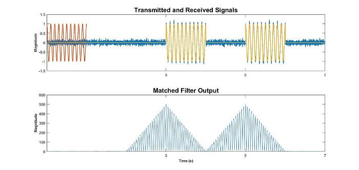 Fig 7: Matched filter output for the objects separated by a distance.
Now consider what happens when the two objects are closely spaced. As evident from Fig 8 below, as the objects draw nearer to each other and the time between the pulses diminishes, the peaks of the pulses will merge. At this juncture, we will no longer be able to distinguish between the two objects and they will be represented as one target.
 Fig 8: Effect on matched filter output when objects are closely spaced.
In reality, this is a radar bandwidth issue. By reducing the pulse width, we can increase the bandwidth and consequently improve resolution. This adjustment allows objects to be positioned closer to each other before their returned pulses overlap, as drawn in Fig 9 below.
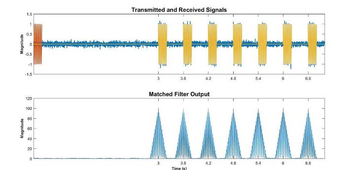 Fig 9: Low pulse width and higher resolution.
However, in the process of reducing the pulse width to enhance resolution, we will experience a decrease in signal-to-noise ratio (SNR). This occurs because decreasing the pulse width of the transmitted pulse also reduces the energy transmitted per pulse, resulting in less powerful signal returning from the target. Consequently, this reduces the maximum range of the radar and there exists a tradeoff between SNR and resolution.
However, a solution exists to achieve better resolution without reducing the pulse width. This solution involves the use of Linear Frequency Modulated (LFM) pulse.
Linear Frequency Modulation
In this waveform, the signal begins with a low frequency that linearly increases throughout the pulse. The template matches this waveform. As drawn in Fig 10 below, when sweeping the template through the received signal, initially there is weak correlation as the overlapped parts are at different frequencies. Strong correlation occurs only when the template and the echo completely overlap. Subsequently, correlation quickly diminishes as the frequencies begin to mismatch again.
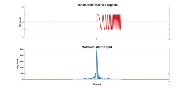 Fig 10: Linear Frequency Modulated waveform and its matched filter output.
In the processed signal, we observe a pulse with a significantly higher peak using the LFM waveform. Additionally, it is compressed to a much shorter duration compared to the original pulse. This is known as pulse compression.
If we introduce some level of noise (depicted in Fig 11 below) as we did with the rectangular pulse, we still discern two peaks above the noise floor when using the LFM waveform. This illustrates why the LFM waveform is less vulnerable to noise compared to the rectangular pulse.
 Fig 11: Effect of noise on LFM waveform and its matched filter output.
Moreover, we gain the advantage of higher resolution as shown in Fig 12. As the two objects draw closer to each other, even when the pulses begin to overlap, the processed signal still exhibits two distinct peaks.
 Fig 12: Effect on LFM waveform and its matched filter output when objects are closely separated.
Interestingly, the resolution obtained from an LFM waveform is not dependent on pulse width. Instead, it depends on the extent of frequency sweep throughout the pulse. Therefore, we can maintain the same power level and still increase the radar bandwidth by sweeping across a broader range of frequencies.

Good explanation of pulse compression in layman language
Thank you Sahil.