Orthogonal Frequency Division Multiplexing (OFDM) has been introduced in a previous article as a technique suitable for high data-rate transmissions over a wireless channel. The two main advantages I mentioned were as follows:
- Simple one-tap equalization, and
- Ability to slice the spectrum and utilize each slice in an independent manner.
Due to these advantages, it was adopted as the preferred modulation in WiFi and 4G-LTE systems. The interesting part is that while many new waveforms were proposed to replace it in 5G NR, OFDM was still the modulation of choice for both downlink and uplink directions with some minor changes. I have provided major advantages and disadvantages of an OFDM system here.
Background
The focus of this article is on pulse shaping in OFDM systems. This discussion heavily relies on the excellent article by Keysight Technologies in Ref. [1]. Originally, OFDM is a block processing scheme and hence there is no extra pulse shaping required after the iDFT at the Tx. Instead, a certain number of subcarriers, both on the positive and negative edges of the spectrum, are left unmodulated to cater for the decay of sinc sidelobes thus alleviating the subsequent digital and analog filtering tasks. In IEEE 802.11a standard, for example, $6$ subcarriers on the negative edge and $5$ subcarriers on the positive edge of the spectrum are assigned as null subcarriers.
Nevertheless, many systems still employ pulse shaping in OFDM systems to smooth the edges at the OFDM symbol boundaries that reduces the out of band power to meet the regulatory requirements. Recall that the pulse shape employed in a single-carrier system is a Raised Cosine in frequency domain. Therefore, from time frequency duality, we already know that the Raised Cosine pulse shape in an OFDM system must be in time domain. We have already covered the topic of pulse shaping in depth here and here and hence briefly describe this operation in the current context.
Cyclic Prefix and Cyclic Suffix
We created the Cyclic Prefix (CP) by appending the last $N_{CP}$ samples from the iFFT output to the beginning of the OFDM symbol. The total symbol duration thus becomes $N+N_{CP}$ samples. For obvious reasons, the next OFDM symbol begins with a different amplitude and phase at the boundary of the current symbol, as shown in Figure below for $N=64$ and $N_{CP}=16$. This discontinuity causes spectral regrowth that violates the spectral mask and creates interference for adjacent channels. Therefore, our task is to assemble consecutive OFDM symbols in a smooth fashion.

To introduce a smooth transition between the current and next OFDM symbol, a cyclic suffix (also known as cyclic postfix) is introduced. Just like a cyclic prefix is the last $N_{CP}$ samples in an $N$ sample symbol, a cyclic suffix is the first $N_{CS}$ samples out of $N$ that are attached at the end.
Let us create an example for $N=64$ and $N_{CP}=16$. The total number of samples in this OFDM symbol is equal to $N+N_{CP}=N_{\text{OFDM}}=80$ as in Figure above and it should remain the same after the windowing operation. Here, we assume a full length cyclic suffix of length $N_{CS} = 16$ samples to understand the concept.
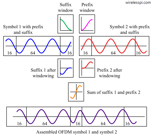
When the first $16$ samples of OFDM symbol $1$ are appended in the end as a cyclic suffix, the symbol becomes $96$ samples long which violates the $N_{\text{OFDM}}=80$ sample condition of the original signal. Instead, an alternative scheme is applied as follows for which a graphical representation is illustrated in the figure below.

- Length $16$ cyclic suffix of symbol $1$ is windowed with the transition part of a Raised Cosine that rolls off from $1$ to $0$.
- Length $16$ cyclic prefix of symbol $2$ is windowed with the transition part of the Raised Cosine that rolls on from $0$ to $1$.
- These two segments are overlapped and summed together to generate a length $16$ portion that is attached between both symbols.
Notice that the waveform is now continuous going from one symbol to the next while the total OFDM symbol duration is still $80$.
Periodicity
Recall that one purpose of the cyclic prefix is to convert linear convolution with the channel into circular convolution. This circular convolution is a result of the periodicity that appears due to the cyclic prefix being the same as the last part of the symbol. However, now a full length cyclic suffix of the first symbol interferes with the cyclic prefix of the next symbol, thus leaving no room for the periodicity to appear.
The solution is to reduce the length of the window, i.e., cyclic suffix, to as less number of samples as possible. For the current example, a length $4$ cyclic suffix implies that the multipath immunity has reduced from $N_{CP}=16$ samples to $N_{CP}-N_{CS}=12$ samples. Only a maximum channel length of $N_{\text{Tap}} =12$ can now induce a single tap flat fading at each subcarrier of the Rx DFT output. This is the price we pay for the spectral smoothing of the waveform.
A very similar technique is known as Windowed-OFDM (W-OFDM) in which windowing is applied in a manner that the window overlaps with the complete OFDM symbol as well as the CP and the cyclic suffix. Moreover, the window amplitude is $-3$ dB at the start and end of the OFDM symbol. For a perfect reconstruction of the OFDM symbol, the cyclic suffix and cyclic prefix are not discarded and instead are added to the start and the end, respectively.
References
[1] OFDM Raised Cosine Windowing: http://rfmw.em.keysight.com/rfcomms/n4010a/n4010aWLAN/onlineguide/default.htm#ofdm_raised_cosine_windowing.htm


Just window the time-domain symbols by raised-cosine windows, with the tails overlapping. You need to “leave room” for them in the time domain, including the CP already. THis is called Filtered OFDM, or FOFDM. In frequency domain, the subcarriers have RC shapes, instead of Sinc shapes, and are still orthogonal, but can have much lower sidelobes.
Thanks for the insightful comment. Filtered-OFDM is also a term used in the literature for a CP-OFDM system with an additional lowpass filter inserted after the CP concatenation that can cause confusion.
What a coincidence. Since a week I was trying to understand this and just now I see your blog. I already went to the keysight website which you have referred, but cundnt understand much. But now with your explanation, it is crystal clear.
Regards
Sumit
That’s interesting : )
Since the weights for the suffix waveform are implied 1 to left of the window and implied 0 to the right of the window, and the weights for the prefix waveform are implied 0 to the left of the window and 1 to right of the window, from what I can see you would want to take that into account when windowing each portion, like using 2:5 and 7:10 of a hann(11)’ window.
Also, would this not need to be done for all symbols/sequences, such as short and long training sequences, last data symbol of this packet with next packet’s short training sequence, etc.? Thus necessitating the need for a globally updated suffix to use in the windowed portion of the next prefix, whatever symbol that may be a part of, so long as it is consecutively transmitted?
You’re right. There are many different possibilities that are ultimately in the hands of the system designer. But usually this can’t go beyond a particular packet.
Thank you for nice article. I have a question about LTE RX system. Which scheme is used to sample timing recovery such as gardner, M&M, Early-Late..?
Single carrier systems use the algorithms you mentioned for timing recovery such as early-late, Gardner, Mueller and Muller, etc. Since LTE is based on OFDM and something similar to DFT-Precoded OFDM, a different kind of timing recovery is required that doesn’t look for pulse peaks like single carrier systems. Instead, with little variations, most such algorithms search for the peak of a timing metric and rely on repetitive correlation within the Rx sequence itself for this purpose.