Today we will discuss three strategies that are usually adopted for handling a wireless channel that is varying with time and hence acting differently on different data symbols. For a channel impulse response $c(t)$, number of multipath $N_{MP}$, channel gains $\gamma_i(t)$ and delays $\tau_i(t)$ for the $i$-th path, respectively, we can write
\begin{equation*}
c_B(t) = \sum _{i=0}^{N_{MP} -1} \gamma_i(t) \cdot \delta(t-\tau_i(t))
\end{equation*}
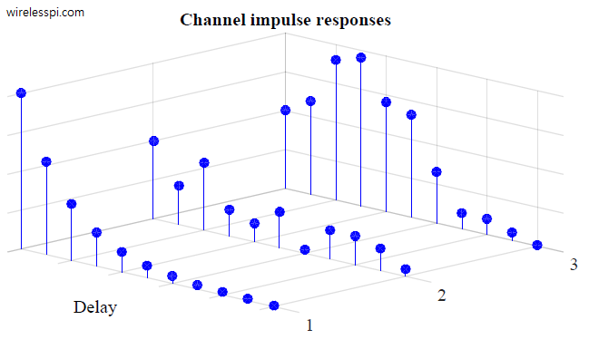
i.e., channel gains $\gamma_i(t)$ and channel delays $\tau_i(t)$ are varying with time albeit at different rates. With the movement in the channel, the taps in a frequency selective channel are changing according to the rotation rates of path phases, as shown in the figure below. Here, we can see different arriving paths at the Rx which form the cumulative tap gain at a particular sampling instant. These rotating vectors are a beautiful manifestation of the complexity a wireless channel exhibits. When I see world clocks at the check-in counter of a hotel, it reminds me of a frequency selective time-varying channel. When you notice a correlation between clock times of this figure, keep in mind that some correlation also exists among the channel taps.

The question we encounter is the following. Designing a Rx for a static channel during a transmission does not seem to be an excessively difficult task. However, when the channel is changing with time, how can a Rx handle this channel that is acting differently on different data symbols? In other words, how should we incorporate channel gains $\gamma_i(t)$ and channel delays $\tau_i(t)$ that are changing with time. With channel taps in hand, we present three routes to solve this issue.
Channel tracking
One widely used solution is to insert symbols known at the Rx called ‘pilots’ at uniform intervals within the Tx waveform. Just like an analog signal is sampled at uniform intervals by an ADC, these known pilots ‘sample’ the channel at these locations and the complete channel response can be constructed through interpolating between the pilots. Consequently, the sampling theorem applies in this scenario that links the number of pilots and the rate of change of the channel. Although it costs some spectral efficiency, the advantage is that the channel can be continuously tracked in time. Then, this estimated channel is assumed known at the Rx and the data symbols are demodulated based on the modulation scheme. This is the strategy deployed in most modern high-rate wireless communication systems such as 4G LTE, 5G NR, WiFi 802.11a/g/n/ac, and so on.
Quasi-static assumption
For a block processing scheme where the data is sent over a series of blocks and the channel changes slowly over each block length, it makes sense to assume that the channel remains constant throughout the duration of each block. Then, a new channel is estimated at the start of the next block which is assumed to hold true for the block duration again. This process can be continued till the end of the whole frame. This quasi-static assumption implies that while a different channel emerges for each block, the same channel acts on the data symbols within each block. An example of this scheme is drawn in the figure below.

Adaptive equalization
Equalizers play a crucial role in mitigating the impact of the wireless channel. For a mostly static channel, these equalizers are preset or fixed at the start of the Rx signal processing and stay so for the duration of the transmission. For a time-varying channel, many equalizers are designed to adapt themselves according to the channel conditions. Here, a special adaptive algorithm makes the equalizer coefficients follow the variations in the channel impulse response. An LMS equalizer in one such example.