We have discussed before that carrier phase synchronization is done at the end of the Rx signal processing chain due to the very nature of the DSP implementation. And that almost all DSP based phase synchronization algorithms are timing-aided. Timing acquisition implies knowing the symbol boundaries in the Rx sampled waveform which is equivalent to identifying the optimal sampling instants where the eye opening is maximum and Inter-Symbol Interference (ISI) from the neighbouring symbols is zero.
In the case of Carrier Frequency Synchronization (CFO), this is not true. From a previous post on the effect of CFO, we know that a CFO can be large or small which leads to the following two synchronization strategies.
Non-timing-aided techniques
For a large CFO, digital processing of the incoming signal must be started without any knowledge of the symbol timing. Imagine in frequency domain how a large CFO reduces the overlap between the incoming signal and the bandwidth processed by digital filters further down the road. At this stage, it is necessary to acquire the carrier frequency to a reasonably close value before any meaningful manipulations on the data can proceed including timing acquisition, necessarily leading to non-timing-aided algorithms.
A further consequence of the timing absence is that no information about the data can be assumed even if there was a preamble or training sequence embedded in the Tx signal stream because the Rx cannot mark which samples of the Rx sequence correspond to those known symbols. Therefore, all non-timing-aided carrier frequency synchronization algorithms are non-data-aided as well.
Finally, downsampling at symbol rate $R_M$ is not feasible since there is no zero-ISI sample yet located. Therefore, non-timing-aided frequency synchronization in general operates at a rate larger than $R_M$, say $L$ samples/symbol.
Timing-aided techniques
When the CFO is small enough (say, less than $15\%$ of symbol rate), timing can be acquired first from an oversampled and slowly rotating constellation. In this case, both data-aided and non-data-aided techniques are possible to implement depending on whether a training sequence is present or not. Having known the symbol boundaries, information about the training sequence can be incorporated into designing a frequency synchronization algorithm or a decision-directed mode can be initialized in the absence of such a training sequence. This scenario also holds during Rx operation in steady state (tracking mode) that implies small CFO values. However, the details of the design depend on the exact scenario since a PLL is also able to track a residual CFO if the loop filter includes an integrator component.
Timing-aided in turn implies that while the matched filtering occurs at $L$ samples/symbol, any processing faster than at symbol rate $R_M$ to adjust the frequency is unnecessary. Therefore, the frequency synchronization block works at exactly the symbol rate $R_M$, or just $1$ sample/symbol to minimize the computational complexity.
Classification
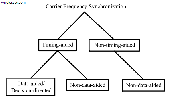
Due to this larger role of timing in the development of frequency synchronization algorithms, I classify the techniques here as timing-aided and non-timing-aided, as opposed to just data-aided/decision-directed and non-data-aided, which is the strategy adopted in carrier phase synchronization scenario. The current classification is illustrated in the figure below. Whether that technique requires information about data or not will be clear from the context.

A Common Strategy
In some cases, a reasonable design is to adopt a two-stage strategy.
- In the first stage, a large CFO is significantly reduced by using a non-timing-aided technique. Although the CFO estimate thus generated is coarse, it is still good enough to allow matched filtering and timing acquisition from the discrete samples.
- In the second stage, a timing-aided scheme is applied to completely compensate for any residual CFO left during the first stage.
You can learn in detail about how a Frequency Locked Loop (FLL) works or see how a carrier frequency offset is compensated in band edge filters.


