An Analog to Digital Converter (ADC) samples a continuous-time signal to produce discrete-time samples. For a digital signal processor, this signal just resides in memory as a sequence of numbers. Consequently, the knowledge of the sample rate $F_S$ is the key to signal manipulation in digital domain.
As far as time is concerned, one can easily determine the period or frequency of such a signal stored in the memory. For example, the period $T$ in the sinusoid of Figure below is clearly $10$ samples and sample time $T_S=1/F_S$ can be employed to find its period in seconds.

- For a sample rate of $F_S=10$ Hz, $T_S = 0.1$ seconds, so
\begin{align*}
T &= 10 ~\frac{\text{samples}}{\text{period}}~ \cdot ~ 0.1 ~\frac{\text{seconds}}{\text{sample}} = 1~ \text{second}
\end{align*}
and its frequency $F = 1/T = 1$ Hz. - For a sample rate of $F_S=500$ Hz, $T_S = 0.002$ seconds, so
\begin{align*}
T &= 10 ~\frac{\text{samples}}{\text{period}}~ \cdot ~0.002 ~\frac{\text{seconds}}{\text{sample}} = 0.02~ \text{seconds}
\end{align*}
with frequency $F = 1/T = 50$ Hz.
As explained before, the samples of both sinusoids will be stored in memory as a sequence of numbers with no difference in discrete domain. Next, we turn our attention to the discrete frequency domain.
Discrete Frequency and the Sample Rate
Remember that the reason we work with discrete-time signals is that the finite memory of a processor can store only a fixed number of time values. Similarly, this finite memory can also store only a fixed number of frequency values and not an infinite range of $F$ values.
For this reason, while we are at sampling in time domain, we also want to sample the frequency domain. Assume that a total of $N$ samples are collected in time domain at a rate of $F_S = 1/T_S$, thus spanning a time duration of $NT_S$ seconds. Then, the lowest frequency that can be represented by these $N$ samples is the one by a sinusoid that completes one full cycle — and no more — during this interval of $NT_S$ seconds. Consequently, its frequency is given by $1/(NT_S)$ Hz and expressed as
\begin{align}
V_I[n]\: &= \cos 2\pi \frac{1}{NT_S}t\bigg|_{t=nT_S} = \cos 2\pi \frac{1}{NT_S}nT_S = \cos 2\pi \frac{1}{N}n\\
V_Q[n] &= \sin 2\pi \frac{1}{NT_S}t\bigg|_{t=nT_S} = \sin 2\pi \frac{1}{NT_S}nT_S = \sin 2\pi \frac{1}{N}n
\end{align}
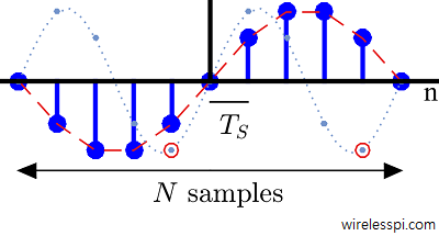
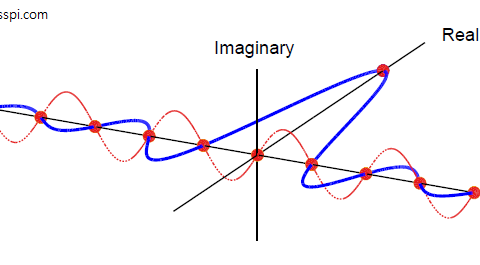
Hence, $1/N$ is the discrete frequency of this sinusoid whose $Q$ part is drawn in Figure below.
Now consider the equation
\begin{equation*}
\frac{1}{NT_S} = \frac{F_S}{N} = F_S\cdot \frac{1}{N}
\end{equation*}
and observe the following.
- While the actual frequency is $F_S(1/N)$, the discrete frequency is $1/N$.
- Frequency resolution, determined by the lowest frequency that can be represented in such a discrete setting, is given by $F_S/N$.
- Viewed as $F_S \cdot 1/N$, we can get more discrete frequency samples that are integer multiples of $1/N$.
\begin{equation*}
0, \frac{1}{N}, \frac{2}{N}, \cdots
\end{equation*}
As a consequence, the frequencies of all such complex sinusoids are integer multiples of the fundamental frequency $1/N$. An example of $Q$ component for $2/N$ is drawn in the background of the above Figure with a dotted line that exhibits $2$ periods within those $N$ samples, indicating $2$ cycles/$N$ samples or $2/N$ cycles/sample.
Extending this concept further, the complex sinusoids whose discrete frequencies are $k/N$ complete $k$ cycles in an interval of $N$ samples (or $k/N$ cycles per sample).
Orthogonality
Let us call the sinusoids with frequencies $1/N$ and $2/N$ as $A$ and $B$, respectively. As we see now, they are orthogonal to each other. Orthogonality implies that their correlation computed at shift $0$ is zero. In other words, the sum of their sample-by-sample products is zero. For a real sinusoid,
\begin{equation}\label{eqIntroductionSinOrthogonality}
\sum \limits _{n=0} ^{N-1} \sin 2\pi \frac{1}{N}n \cdot \sin 2\pi \frac{2}{N}n = 0
\end{equation}
This can be verified from the last figure. Observe that $B$ has $2$ periods within $N$ samples. In its first period, the products of its samples are taken with negative samples of $A$. In its second period, the same products are taken with positive samples of $A$ with exactly the same magnitude. In this way, this sum turns out to be zero.
This is evident from circles drawn around two of its samples in Figure above. Verify that the corresponding samples of the sinusoid $A$ have opposite signs. Since the original workhorses of DSP are the complex sinusoids and not the real ones, we now analyze orthogonality in that context.
In the article on correlation, we found that the expression for correlation of two complex signals involves conjugation of the second signal. Therefore, to examine this correlation at shift $0$ (i.e., orthogonality), we need to apply the multiplication rule of complex signals: due to the conjugation of the second signal, the $I$ term of the result is $I\cdot I$ $+$ $Q\cdot Q$ and the $Q$ term of the result is $Q\cdot I – I\cdot Q$. For two complex sinusoids with discrete frequencies $k/N$ and $k’/N$, this correlation at lag $0$ is
\begin{align*}
\sum _{n=0}^{N-1}\left[\cos 2\pi \frac{k}{N}n\cdot \cos 2\pi \frac{k’}{N}n + \sin 2\pi \frac{k}{N}n\cdot \sin 2\pi \frac{k’}{N}n\right]\\
\sum _{n=0}^{N-1}\left[\sin 2\pi \frac{k}{N}n \cdot \cos 2\pi \frac{k’}{N}n – \cos 2\pi \frac{k}{N}n \cdot \sin 2\pi \frac{k’}{N}n\right]
\end{align*}
Using the identities $\cos A \cos B + \sin A \sin B = \cos (A-B)$ and $\sin A \cos B – \cos A \sin B = \sin (A-B)$,
\sum _{n=0}^{N-1}\cos 2\pi \frac{k-k’}{N}n &= \begin{cases}
N & k = k’ \\
0 & k \neq k’
\end{cases}\\
\sum _{n=0}^{N-1}\sin 2\pi \frac{k-k’}{N}n &= 0
\end{align}
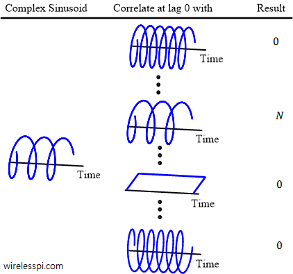
where we have used the fact the sum of samples of $\cos(\cdot)$ and $\sin(\cdot)$ above is zero due to an integer number of periods within $N$ samples. Also, $\cos 0 =1$ when $k=k’$ that adds up to $N$. This concept is illustrated in Figure below.
We have proved the following result.
“All complex sinusoids having frequencies as integer multiples of a fundamental frequency $F_S(1/N)$ are orthogonal to each other.”
We now move towards drawing this discrete frequency axis.
Discrete Frequency Axis
With $N$ discrete time domain samples, are there infinite complex sinusoids out there that are orthogonal to each other? The answer is no and we claim that their number is only $N$. To verify, let us explore one such option with a discrete frequency $N/N=1$.
\begin{equation*}
\sin 2\pi \frac{N}{N}n = \sin 2\pi n = 0
\end{equation*}
Hence, a complex sinusoid with discrete frequency $0$ is the same as the one with discrete frequency $1$. For the next candidate $(N+1)/N$, use $\sin(A+B) = \sin A\cos B +\cos A \sin B$.
\begin{align*}
\sin 2\pi \frac{N+ 1}{N}n &= \sin 2\pi n \cos 2\pi \frac{1}{N}n + \cos 2\pi n \sin 2\pi \frac{1}{N}n \\
&= \sin 2\pi \frac{1}{N}n
\end{align*}
because $\sin 2\pi n = 0$ and $\cos 2\pi n = 1$. We conclude that there are only $N$ distinct frequencies from $0$ to $N-1$ (or $-N/2$ to $N/2-1$ as we will shortly see). Onwards, they just repeat themselves.
Interestingly, we learned that for $N$ samples in discrete time domain, there are $N$ samples in the discrete frequency domain as well! These $N$ samples represent discrete frequencies of complex sinusoids that are integer multiples of one fundamental frequency $1/N$ and hence are all orthogonal to each other.
From $N$ discrete frequencies found above, we could construct a discrete frequency axis with the following members.
\begin{equation*}
0, \frac{1}{N}, \cdots \cdots, \frac{N-1}{N}
\end{equation*}
which are exactly the same as
\begin{equation*}
-1, -1+\frac{1}{N},\cdots \cdots, \frac{-1}{N}
\end{equation*}
due their periodicity. However, there is a reason we choose to work with an axes centered around $0$. The unique range of continuous frequency $F$ after sampling a signal is $-0.5F_S \le F < +0.5F_S$, or
\begin{equation}
-0.5 \le \frac{F}{F_S} < +0.5 \label{eqIntroductionDiscreteFreqRange}
\end{equation}
Since there are $N$ discrete frequencies, $-0.5 \le F/F_S < +0.5$ is divided into $N$ equal intervals (assuming $N$ is even) by sampling at instants
\begin{align}
-0.5,-0.5+\frac{1}{N},\cdots,-\frac{1}{N},0,\frac{1}{N},\cdots,+0.5-\frac{1}{N} \label{eqIntroductionDiscreteFreqAxis}
\end{align}
to obtain the discrete frequency axis. Obviously, the discrete frequency resolution is $1/N$. So discrete frequency is basically the spectral content in the baseband sampled at $N$ equally spaced frequency points (the term $+0.5$ is absent because it is the same as $-0.5$ owing to the axis periodicity).
Eq \eqref{eqIntroductionDiscreteFreqAxis} can also be written as
\begin{align}
\frac{-N/2}{N}, \frac{-N/2+1}{N}, \cdots, -\frac{1}{N},0,\frac{1}{N},\cdots, \frac{N/2-1}{N} \label{eqIntroductionDiscreteFreqAxis2}
\end{align}
Consequently, the index $k$ of discrete frequency axis is given by $[-N/2,N/2-1]$, or
\begin{align*}
k &= -\frac{N}{2},-\frac{N}{2}+1,\cdots,-1,0,1,\cdots,\frac{N}{2}-1 \\
\frac{k}{N} &= -0.5,-0.5+\frac{1}{N},\cdots,-\frac{1}{N},0,+\frac{1}{N},\cdots,+0.5-\frac{1}{N}
\end{align*}

This is drawn in Figure above. Comparing the above equation with Eq \eqref{eqIntroductionDiscreteFreqRange}, we arrive at the relation between discrete frequency $k/N$ and continuous frequency $F$ as
\frac{k}{N} = \frac{F}{F_S}
\end{equation}
The units of discrete frequency $k/N$ from Eq \eqref{eqIntroductionFreqRelation} are
\begin{align*}
\frac{\text{cycles}}{\text{second}} ÷ \frac{\text{samples}}{\text{second}} = \frac{\text{cycles}}{\text{sample}}
\end{align*}
Eq \eqref{eqIntroductionFreqRelation} is one of the two most fundamental relations in digital signal processing, the other being the sampling theorem. These are the two interfaces between continuous and discrete worlds.
Establishing the relationship between continuous and discrete frequencies gives the frequency domain as a sequence of numbers stored in a processor memory.
When in doubt about continuous and discrete frequency domains, refer to Eq \eqref{eqIntroductionFreqRelation}!
If the discrete frequency $k/N$ and the sample rate $F_S$ are known, the actual continuous frequency can be found from Eq \eqref{eqIntroductionFreqRelation}.
\begin{equation*}
F = F_S \cdot \frac{k}{N}
\end{equation*}
For example, with $F_S = 3$ kHz and $N = 32$,
\begin{align*}
k = 0 \quad \rightarrow \quad F &= 3000 \cdot \frac{0}{32} = 0 ~\text{Hz} \\
k = 1 \quad \rightarrow \quad F &= 3000 \cdot \frac{1}{32} = 93.75 ~\text{Hz} \\
k = 2 \quad \rightarrow \quad F &= 3000 \cdot \frac{2}{32} = 187.5 ~\text{Hz}
\end{align*}
Each $k$ is therefore called a {frequency bin and the value $N$ determines the number of input samples and the resolution of discrete frequency domain. Understanding the sampling theorem and Eq \eqref{eqIntroductionFreqRelation} will make the further concepts much easier to grasp.
In conclusion, the range of unique discrete frequencies $k/N$ is
\begin{equation}\label{eqIntroductionFreqRangeDiscrete}
-0.5 \le \frac{k}{N} < +0.5
\end{equation}
This set of complex sinusoids is drawn in Figure below highlighting the discrete frequency index $k$. The negative indices of $k$ illustrate the clockwise direction of rotation while the positive indices of $k$ point towards the anticlockwise rotation. Observe that the rate of oscillation in discrete-time signals decreases with $k/N$ going from $-0.5$ to $0$ and increases from $0$ to $+0.5$, remembering that $k/N = -0.5$ is the same as $k/N = +0.5$.
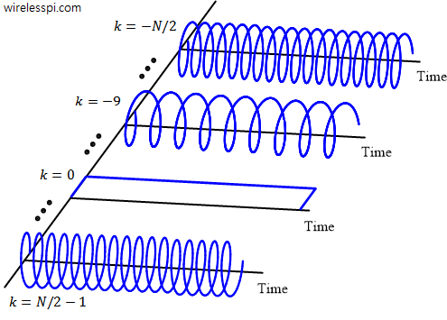
Keep this figure in mind for most of the applications of signal processing techniques as they represent a complete discrete frequency set. And it will help you in surprising ways!
Some people are more comfortable with 2D figures instead of 3D ones. So this set of complex sinusoids with both $I$ and $Q$ components is shown in Figure below for $N = 8$.
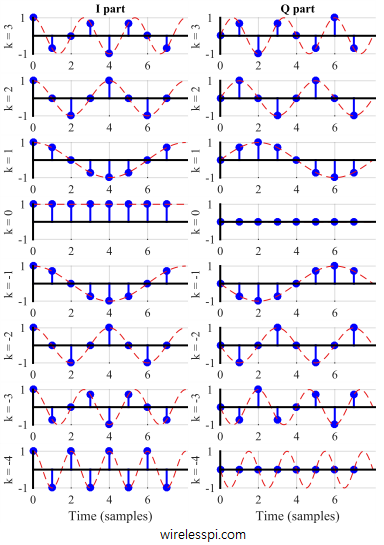
Following are a few key observations in this figure.
- For $k = 0$, the $I$ sinusoid is $1$ because $\cos 0 = 1$, while $Q$ sinusoid is $0$ because $\sin 0 = 0$.
- Just like $k=1$ implies that the $I$ and $Q$ waveforms, $\cos 2\pi\cdot1/N$ and $\sin 2\pi\cdot1/N$, complete one full cycle during $N = 8$ samples, each complex sinusoid with discrete frequency $k/N$ spans $k$ complete cycles in an interval of $N$ samples.
- For negative values of $k$, $I$ sinusoids remain unchanged while $Q$ sinusoids change sign. In the context of complex sinusoids, this follows from the definition of negative frequencies as the ones with clockwise rotation.
- Finally, to understand what the units of discrete frequency `cycles/sample’ mean, consider for example the case of $k=2$ in this figure. Observe that for $N=8$, we have the discrete frequency equal to $k/N=2/8=1/4$ cycles/sample. Notice that this sinusoid completes a quarter cycle from one sample to the next and hence the frequency of $1/4$ cycles/sample.
Next, we consider an example to highlight the impact of aliasing on a discrete-time signal and why it is not necessary for all continuous frequencies to translate into corresponding discrete frequencies.
Consider a signal
\begin{equation*}
s(t) = 2 \cos(2 \pi 1000 t) + 7 \sin(2\pi 3000 t) + 3 \cos(2 \pi 6000t)
\end{equation*}
It is clear that continuous frequencies present in this signal are $F_1 = 1$ kHz, $F_2 = 3$ kHz and $F_3 = 6$ kHz. Since the maximum frequency is $6$ kHz, the sampling theorem gives the Nyquist rate as $2\times6$ kHz = $12$ kHz.
Now suppose that this signal is sampled at $F_S = 5$ kHz, the folding frequency is then given by $0.5F_S = 2.5$ kHz. Sampling the signal at equal intervals of $t = nT_S$
\begin{align*}
s[n] &= s(t)|_{t = nT_S} = s\left(\frac{n}{F_S}\right) \\
&= 2 \cos 2 \pi \frac{1}{5} n + 7 \sin 2 \pi \frac{3}{5}n + 3 \cos 2 \pi \frac{6}{5}n \\
&= 2 \cos 2 \pi \frac{1}{5} n + 7 \sin 2 \pi \left(1 – \frac{2}{5}\right)n + 3 \cos 2 \pi \left(1+\frac{1}{5}\right)n
\end{align*}
where the adjustment is done to bring all discrete frequencies within the range $-0.5$ to $0.5$. Next,
\begin{align*}
s[n] &= 2 \cos 2 \pi \frac{1}{5} n + 7 \sin 2 \pi \left(-\frac{2}{5}\right)n + 3 \cos 2 \pi\left(\frac{1}{5}\right)n \\
&= 5 \cos 2 \pi \frac{1}{5} n – 7 \sin 2 \pi \frac{2}{5}n
\end{align*}
If this signal is reconstructed in continuous-time domain, the frequencies present are $k/N = 1/5$ and $k/N = -2/5$. From Eq \eqref{eqIntroductionFreqRelation}, these appear as continuous frequencies at $F_1 = 5\times1/5=1$ kHz and $5\times-2/5 = -2$ kHz. Since only $1$ kHz is less than $0.5F_S$ and hence within aliasing-free range, it is still there after sampling. The other two are above the folding frequency and hence aliased to $F_2-F_S = 3-5=-2$ kHz and $F_3-F_S=6-5=1$ kHz.
Two final remarks are in order here.
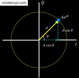
- Dealing with complex numbers through an $IQ$ notation has several advantages. For example, it can avoid the standard complex expressions like $\exp\left(j\theta\right)$ at a cost of additional maths. More importantly, it describes how the mathematical operations are implemented in actual electronic circuits. Also, it reminds us how phase is equally important in signal analysis.
- Every time I write an expression involving a discrete frequency, I express it either as $2\pi \frac{k}{N}n$ or $2\pi (k/N)n$, instead of $2\pi kn/N$ that is used in most texts. The former clearly indicates the presence of a discrete frequency $k/N$ analogous to the variable $F$ in $2\pi Ft$, while it is easy to lose this meaning in the latter.

Thanks Qasim for this very clear explanation.
Is really very informative and formative.
Regards
PS I have bought your book and reading it.
Thanks for your kind words!