In 1978, Fred Harris was a relatively unknown faculty member at the San Diego State University when he published his landmark paper titled On the use of windows for harmonic analysis with the discrete Fourier transform. That paper made him a superstar in DSP community.
It presented a brief overview of signal windows and their impact on the detection of harmonic signals in the presence of broad-band noise and nearby harmonic interference. More importantly, he pointed out several common errors in the application of windows when used in the context of Discrete Fourier Transform (DFT).
Today I am going to write about how the paper started: by clarifying a common misconception about regular signal symmetry vs DFT symmetry that baffled the DSP scientists — even the experienced ones who wrote professional DSP software — in those days. Fred’s description of the error was both succinct and beautiful. And the reader will appreciate the underlying aspects of signal analysis that stay hidden from the perspective of many DSP folks.
Background
In time domain, a discrete-time signal consists of $N$ uniformly spaced samples of the observed signal. In frequency domain, the basic idea of Fourier Transform is as follows:
- Most signals of practical interest can be decomposed into a sum of complex sinusoids of different frequencies.
- A set of $N$ orthogonal complex sinusoids can be constructed within a span of $N$ time domain samples.
- Each sample on the discrete frequency axis denotes the discrete frequency $k/N$ of such a complex sinusoid.
- The first sinusoid completes 1 cycle in that time, i.e., it has a period equal to $NT_S$ seconds, and a frequency of $1/NT_S$ Hz.
- The second sinusoid completes 2 cycles in that $NT_S$ interval, or a period equal to half that duration as shown above.
- For an arbitrary $k$, we get
\[
2\pi f_kt = 2\pi \frac{k}{NT_S}t
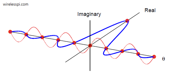
\] - An all-ones sequence has a Fourier Transform that is a sinc signal. This is what we get in the real part as plotted in the figure below.
- From Euler’s identity, we know that a real sine wave with frequency $\omega$ has a spectrum that are two impulses at $+\omega$ and $-\omega$, respectively, in the imaginary part.
\[
\sin \omega t = j\frac{e^{-j\omega t}-e^{+j\omega t}}{2}
\]Using time-frequency duality, two impulses in time domain at $n=\pm N/2$ result in a sine wave in frequency domain with period $2/N$! This is what we see in the imaginary part of the DTFT below.
So for $N$ time domain samples, we have $N$ frequency domain samples. But what do these spectral samples mean?
The DFT gives us the amplitude and phase contribution from each complex sinusoid that add up to form the observed signal.
Mathematically, we can write
\begin{equation*}
X[k] = \sum \limits _{n=0} ^{N-1} x[n]e^{-j2\pi\frac{k}{N}n}
\end{equation*}
where the discrete-time complex sinusoid $e^{j2\pi\frac{k}{N}n}$ above has the following real and imaginary parts.
\begin{equation*}
\begin{aligned}
&\cos 2\pi\frac{k}{N}n\\
&\sin 2\pi\frac{k}{N}n
\end{aligned}
\end{equation*}
Why the minus sign in DFT definition? Because the opposite rotation from the minus sign cancels the original complex sinusoid sample-by-sample, thus leaving us only with its complex magnitude contribution. To investigate the difference between regular signal symmetry and DFT symmetry, we will first have to understand the above expressions.
Set of Sinusoids
Let us take an observation interval equal to $T$ seconds. For a sample rate of $F_S=1/T_S$ and $N$ equally-spaced samples,
\[
T = NT_S
\]
\[
2\pi f_1t = 2\pi \frac{1}{NT_S}t
\]
\[
2\pi f_2t = 2\pi \frac{2}{NT_S}t
\]
Sampling at $t=nT_S$ gives us the $k$-th DFT sinusoid.
\[
\begin{aligned}
\cos 2\pi\frac{k}{NT_S}nT_S&=\cos 2\pi\frac{k}{N}n\\
\sin 2\pi\frac{k}{NT_S}nT_S&=\sin 2\pi\frac{k}{N}n
\end{aligned}
\]
All these signals form an orthogonal set, a set of signals whose sum of sample-by-sample products is zero.
Problem with the Interval Length
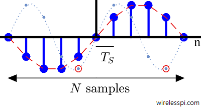
Notice from the figure below that this interval of $NT_S$ seconds is not the same as the interval covered by $N$ samples. Here, the continuous-time cosine signal is even about its midpoint (sample 8 below). But the discrete-time cosine signal has no sample at $N$-th location because the index starts at 0 and the last sample appears at $N-1$.

Recall that the DFT is periodic in frequency domain. In addition, the spectral sampling creates aliases in time domain too. In other words, the DFT, while knowing nothing about the signal outside the window of $N$ samples, implicitly gives rise to periodicity in time domain as well.
Therefore, the missing sample at $N$-th location can be considered as the first sample of the periodic extension of this signal, i.e., the sample at location $n=16$ in the above figure is the same as the sample at $n=0$, see the figure below. As a consequence, while the continuous-time cosine in the last figure clearly looks periodic, the discrete-time cosine looks ‘wider’ on the left side. It does not seem to be periodic.

This apparent lack of symmetry made many researchers and developers understand and interpret the DFT symmetry in a wrong manner which lead to numerous errors in the literature and software libraries in the past.
DFT Symmetry vs Conventional Symmetry
– Conventional even symmetry implies that the sequence has matching right and left halves about a midpoint.
– A DFT-even sequence is a conventional even sequence with its right endpoint removed.
The question is the following: Why does this right endpoint removal not cause asymmetry in the signal and have no impact on resulting Fourier Transform?
To resolve this inconsistency, recall that the DFT is related to the Discrete-Time Fourier Transform (DTFT) that is defined as
\[
X(\theta) = \sum \limits _{n=0} ^{N-1} x[n]e^{-j\theta n}
\]
Sometimes it is known as the finite Fourier Transform. Comparing with the DFT definition above, we conclude that the DFT samples the DTFT at
\[
\theta = 2\pi \frac{k}{N}
\]
Rise of the Odd Part
Let us take the DTFT of a finite length sequence, say an all-ones sequence (that is DFT-even), by treating the missing endpoint at $n=+N/2$ as a zero sample as shown in the figure below.

This makes the signal asymmetric and hence we decompose it into even and odd parts. Recall that even and odd parts of any real signal are defined by the following expressions.
\[
\begin{align*}
\text{Even}\{x[n]\}&=\frac{x[n]+x[-n]}{2} \\
\text{Odd}\{x[n]\}&=\frac{x[n]-x[-n]}{2}
\end{align*}
\]
These expressions are also drawn in the figure above. Unlike a conventional even sequence whose odd part is zero, we get an impulse at $n=-N/2$ and another impulse at $n=+N/2$ in the odd part of this DFT-even sequence!
Sine in the Fourier Transform
Next, let us draw the DTFT of this sequence and see what happens.

Let us now see how this sine wave does not appear in the final result.
The Sine Wave Disappears
To find the DFT, we sample the DTFT at intervals with spacing $2\pi/N$ (or $1/N$ in normal units). But the sine wave with period $2/N$ completes one cycle in a span of $2/N$ in frequency domain while the zero-crossings of the sinc are $1/N$ apart. As a consequence, this signal is sampled in frequency domain at all zero-crossings of the sine wave. As shown in the figure below, this sine wave does not appear anymore in the DFT of the original DFT-even sequence!

This is the beauty of symmetry in the Fourier Transform. While it goes unnoticed in derivations and computations, I hope the reader enjoyed exploring what exactly is going on behind the curtain.


Could you explain more on this please. It will be very helpful
“Why the minus sign in DFT definition? Because the opposite rotation from the minus sign cancels the original complex sinusoid sample-by-sample, thus leaving us only with its complex magnitude contribution”
Imagine that the input signal to DFT is a complex sinusoid with discrete frequency 3/N. From the DFT definition, it is multiplied with N complex sinusoids with discrete frequencies from 0 to (N-1)/N but with negative signs. For all others, the result is zero due to orthogonality. Only for sinusoid with frequency 3/N, the output cancels sample-by-sample at each moment, resulting in a constant that after summation gives a large value.
But what about other signals. Remember that all signals are made up of sums of sinusoids. Therefore, same process is repeated for each such sinusoid.
Hope that helps.