For each generation of cellular networks, there is a significant jump in data rates due to the rising demand and novel use cases from emerging applications and associated ecosystems. Some examples in 6G networks are driverless and collaborative transportation, joint communication, localization and sensing, e-health and tactile Internet. Therefore, at the start of each concept-to-deployment cycle, engineers and researchers propose, evaluate and experiment with new ideas, preferably one or two disruptive technologies that can help them meet their targets.
- For 5G systems, these technologies appeared in the form of a large number of antennas (massive MIMO) and usage of higher frequency bands in 10s of GHz range (mmWave communication).
Massive MIMO enables beamforming in desired directions while simultaneously suppressing interference through spatial nulls. In addition, it opens the possibility to spatially multiplex several users for higher network throughput.
Larger bandwidths in mmWave bands permit unprecedented data rates for individual users and increased frequency reuse through smaller cells owing to the rapid attenuation of signals.
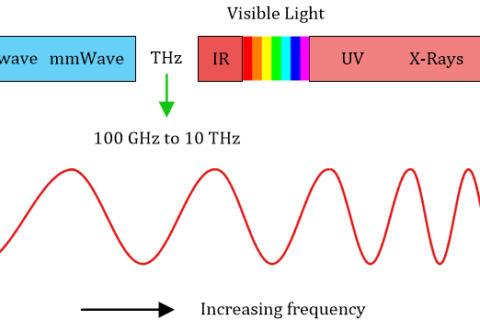
- For 6G systems, two active areas of research were initially proposed: (a) an even-higher number of antennas (doubly-massive MIMO), and (b) even higher frequency bands in THz range. At the same time, the idea of Reconfigurable Intelligent Surfaces (RIS), also known as Intelligent Reflecting Surfaces (IRS) and software-controlled metasurfaces, started floating around.
We start with a little background, then we turn towards the signal model and how it is related to wireless transmission. We describe how RIS can assist in realizing the signal gains at the Rx side. Finally, we conclude the discussion with some criticism and drawbacks of this technology.
Background
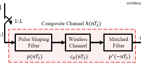
Up until now in the history of wireless communications, the focus of the designer has been to develop transmitters and receivers that can reliably communicate with each other over a harsh wireless channel. As shown in the figure below, these transmitters and receivers partition this task between analog and digital signal processing sections for this purpose. In the past few decades, the main thrust has been to push the DSP part towards the antenna, i.e., Software Defined Radio (SDR), at both ends of the link.

Now it seems that signal processing has broken free from the limits of transmit and receive devices. Instead, the wireless channel itself can be partially engineered according to our own requirements!
At first glance, it seems perplexing that any company would invest huge amounts of money to install these intelligent reflecting surfaces on large buildings in a city. To enable people watch videos, play games and explore new applications on the move?

However, when we look back and explore the direction towards which cellular systems are developing, we find that RIS is not an entirely new concept. For example, 4G LTE introduced Coordinated Multi-Point (CoMP) in which separate base stations coordinate in transmission or reception of signals optimized for not one user but for an entire group of active customers. This results in interference reduction and a better utilization of network resources, particularly for cell edge users. Sometimes called Distributed MIMO, such a system can deliver significant gains in small cell environments. This is why it plays an important role in 5G systems too.
At the same time, the smaller cell sizes approach a cell-free network in the limit. This can be a network with a large number of single antenna access points distributed within an area that are connected to the same processing unit for joint transmission and reception. This is known as cell-free massive MIMO.
Looking from this angle, the intelligent reflecting surfaces installed at different locations are not much different than passive access points that help in signal reception in an energy efficient manner. This efficiency comes from both low manufacturing costs as compared to base stations and low recurring expenses in terms of energy consumption.
To understand how Reconfigurable Intelligent Surfaces (RIS) help us in shaping wireless signal paths, we start with the signal model under this study.
Signal Model
We consider a system in which both the Tx and the Rx are single antenna devices. In a practical scenario, it is quite likely to have a large number of antennas in at least one of the devices. Nevertheless, a single antenna system allows us to understand the fundamental idea without involving matrices. The results can then be generalized to MIMO systems.
Also, we investigate the impact of RIS in a narrowband setting. In general, given the transmitted signal $s(t)$ and a time-invariant wireless channel with impulse response $h(t)$, the received signal $r(t)$ is given by the convolution between $s(t)$ and $h(t)$. Here, I will bypass the complicated derivations and show the main idea in a simple manner.
The channel is composed of $N_P$ paths, each having its own amplitude $\eta_i$ and delay $\tau_i$. Here, we assume that the channel is quasi-static, i.e., it stays constant within the duration of one transmission and changes from one block to the next.
As a consequence, the received signal $r(t)$ is a sum of $N_P$ copies of the transmitted signal $s(t)$ scaled and shifted as
\[
r(t) = \sum _{i=0}^{N_P -1} \eta_i \cdot s(t-\tau_i)
\]
When the delays $\tau_i$ are small as compared to the symbol time $T_M$ (duration of one bit for binary modulations), then
\[
s(t-\tau_i) \approx s(t)
\]
And we have the situation drawn in the figure below with a Line of Sight (LoS) path along with two multipath components.

In this scenario,
\begin{equation}\label{equation-flat-fading-time}
r(t) \approx \sum _{i=0}^{N_P -1} \eta_i \cdot s(t) = h \cdot s(t)
\end{equation}
where $h$ is a constant expressed as
\begin{equation}\label{equation-flat-fading-channel}
h = \sum _{i=0}^{N_P -1} \eta_i
\end{equation}
In words, the above expression tells us that as long as the largest channel delay is a small faction of the symbol time, the signal is not too far spread in time (with respect to inverse signal bandwidth) and all such summations give rise to only one channel tap $h$.
For the sake of simplicity, I skipped the role of carrier frequency $f_c$ above. Remember that the wireless channel interacts with the Tx signal in passband (higher frequency region). At the Rx, this signal is downconverted to baseband through a frequency translation by $-f_c$.
To see what happens after such a downconversion, consider a complex sinusoidal Tx signal $s(t)=e^{j2\pi f_ct}$. The Rx signal after passing through the channel is
\[
\begin{aligned}
r(t) &= \sum _{i=0}^{N_P -1} \eta_i e^{j2\pi f_c(t-\tau_i)} \\
&= \underbrace{\sum _{i=0}^{N_P -1} \eta_i e^{-j2\pi f_c \tau_i}}_{h} e^{j2\pi f_c t} = h\cdot e^{j2\pi f_c t}
\end{aligned}
\]
We conclude that the channel $h$ is actually a complex constant and Eq (\ref{equation-flat-fading-channel}) is modified as
\[
h = \sum _{i=0}^{N_P -1} \eta_ie^{-j2\pi f_c \tau_i}
\]
Going back to Eq (\ref{equation-flat-fading-time}), for a single modulation symbol $s$ sent over the air, the received signal $r$ is given by
\begin{equation}\label{equation-flat-channel}
r = h\cdot s + \text{noise}
\end{equation}
Many infrastructure based wireless systems use this signal model either directly or by slicing a wide spectrum through Orthogonal Frequency Division Multiplexing (OFDM). A simple block diagram of such a setup is drawn in the figure below.

Next, we proceed towards the role of RIS in transforming the wireless channel.
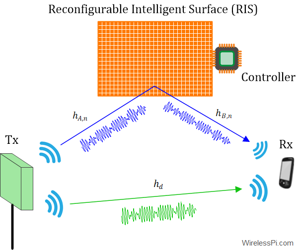
RIS-Assisted Wireless Transmission
As opposed to the above description, we have to consider the impact of three media here, not one.
- The wireless channel from the RF Tx to the $n$-th RIS element is denoted by $h_{A,n}$ in the figure below. From Eq (\ref{equation-flat-channel}), we could write
\[
r = \sum _{n=1}^N h_{A,n} \cdot s + \text{noise}
\]Here, the RIS parameters and the channel from the RIS to the Rx are yet to come.
- Attenuation and time delay applied by the $n$-th RIS component are denoted by $\gamma_n$ and $\tau_n$, respectively. For a narrowband transmission, this time delay imparts a phase shift as
\begin{equation}\label{equation-tau-theta}
e^{j\theta_n}=e^{-j2\pi f_c\tau_n}
\end{equation}If this expression is not clear to you, refer to the derivation of the complex channel above. In this passive reflection scheme:
— the amplitude $\gamma_n$ is between 0 and 1 because it cannot amplify the incoming signal, so from here onwards, we will assume the best case scenario of $\gamma_n=1$, and
— the phase $\theta_n$ is naturally constrained to lie between 0 to $2\pi$.The cumulative signal can now be modified for an $N$-element RIS.
\[
r = \sum _{n=1}^N h_{A,n} \cdot \gamma_n e^{j\theta_n} \cdot s + \text{noise}
\]where the impact of the channel from the RIS to the Rx is not yet included.
- The wireless channel from the $n$-th RIS element to the Rx is denoted by $h_{B,n}$ in the figure above. The above expression gives us
\begin{equation}\label{equation-narrowband-irs}
r = \underbrace{\sum _{n=1}^N h_{A,n} \cdot \gamma_ne^{j\theta_n} \cdot h_{B,n}}_{\Lambda} \cdot s + \text{noise}
\end{equation}We can observe that the final frequency flat channel is a product of three terms: Tx to $n$-th RIS element channel, contribution from element $n$ and $n$-th element to Rx channel. Keep in mind that both $h_{A,n}$ and $h_{B,n}$ above are complex scalars.
- Remember that the RIS is not the only surface present in the environment. The final expression involves the direct channel $h_d$ from the Tx to the Rx too (that would have originated from the vector sum of several paths), see the figure above. Therefore, we obtain the final expression as
$$
\begin{equation}
\begin{aligned}
r &= \left[\sum _{n=1}^N h_{A,n} \cdot \gamma_ne^{j \theta_n} \cdot h_{B,n} +h_d\right] s + \text{noise} \\
\\
&= \left(\Lambda + h_d\right) s + \text{noise}
\end{aligned}
\end{equation}\label{equation-narrowband-irs-channel}
$$This is the expression we will use for deriving the reflection parameters.

RIS Design from a DSP Viewpoint
From a signal processing viewpoint, what should be the optimal reflection parameters $\gamma_n$ and $\theta_n$? To answer this question, I assume that the reader has an understanding of complex numbers.
There are two complex scalars in Eq (\ref{equation-narrowband-irs-channel}).
- The cumulative channel from the Tx to the RIS onto the Rx, $\Lambda$ $=$ $\sum _{n=1}^N h_{A,n} \cdot \gamma_ne^{j\theta_n} \cdot h_{B,n}$. This can be controlled through the RIS response.
- The direction channel from the Tx to the Rx, $h_d$. We have no control over this part.
Our objective here is to maximize the magnitude of $\Lambda+h_d$ so that all there are no amplitude cancelations from phase misalignments and the signal arrives at the Rx with maximum power.
For a sum of two complex numbers $a$ and $b$,
\[
\begin{aligned}
|a+b|^2 &= \left(a+b\right)^*\left(a+b\right) \\
&= |a|^2 + |b|^2 + a^*b + ab^* = |a|^2 + |b|^2 + 2 \Re \{a^*b\} \\
&= |a|^2 + |b|^2 + 2|a||b|\cos \psi
\end{aligned}
\]
where $\psi$ is the angle between $a$ and $b$ on a complex plane. The third step follows from the fact that summing a complex number with its conjugate cancels the imaginary part and produces the real part.
The above magnitude can be maximized if $\cos \psi=1$, or $\psi=0$. For this to happen, $a$ and $b$ should have similar angles. This is drawn in the figure below where a misalignment between the two phases is shown to have an amplitude loss as compared to the aligned phases situation.

In our context, the magnitude $|\Lambda+h_d|^2$ should be maximized with the following conditions.
- The magnitudes $\gamma_n=1$ for all $n$.
- The phase of $\Lambda$ is given by
\[
\measuredangle \Lambda = \measuredangle h_d
\]where $0 \le \theta_n \le 2\pi$ for all $n$.
Since $\Lambda=\sum _{n=1}^N h_{A,n} \cdot \gamma_n e^{j\theta_n} \cdot h_{B,n}$, for controllable phase $\theta_n$ of each individual RIS element $n$, we have
\[
\measuredangle h_{A,n} + \theta_n + \measuredangle h_{B,n} = \measuredangle h_d
\]
Then the phases of all complex scalars within $\Lambda$ have the phase $\measuredangle h_d$ and hence add up in phase with each other. Their sum also has the same phase. This leads us to the optimal solution as
\theta_n = \measuredangle h_d ~-~ \measuredangle h_{A,n} ~-~ \measuredangle h_{B,n}
\]
We can see that the RIS acts as a beamformer: coherent summation of signals at the Rx is achieved by aligning the phases of multiple paths. This passive beamforming is quite similar to Maximum Ratio Combining (MRC) that is known as virtual or generalized beamforming.
Criticism
While the idea of RIS is attractive, only time will tell whether it will actually come to fruition. There are a fair number of skeptics who point out the following flaws.
- Channel estimation from the Tx to RIS and from the RIS to Rx is not trivial. It involves practically having an entire modem hardware and signal processing chain, a point where their boundaries with regenerative relaying start to blur.
- Whether they provide spatial multiplexing and interference mitigation in a more cost-effective manner as compared to cell-free massive MIMO remains to be seen.
- When it comes to wideband channels, RIS are at a particular disadvantage because each element needs to be identically configured over the entire frequency band. Moreover, a wider spectrum is only available as we go up towards higher frequencies in mmWave and THz ranges. But signal propagation at those frequencies is severely limited. If the signal cannot even travel over those distances, what role could RIS play in realizing the gains claimed is not clear.
- It is not clear who is going to bear the huge cost of the material and whether that cost is justified. Remember that when it comes to marginal gains, businesses like to continue with the status quo. Only when these gains cross a certain threshold, say 8-10 times, can an interest be generated.
Thanks to Emil Bjornson for his comments on some of the above points.
Keep it up, great work. Could you please let me know, how can i buy your books?
Thanks. You can click here and scroll down to Complete.
Great explanation of this one of the hottest topics in 6g research. I also want to buy your books and explore content.
Please see my reply to the above comment.
May i reference your site and use the first diagram in a technical presentation to the FCC? thank you
Yes you can.
thank you
thanks a lot for those explanation.
i like to see all this in a simulation video to more understand all equation